Inductance type wireless ball rod instrument

A wireless ball, inductive technology, used in instruments, measuring/indicating equipment, program control, etc., can solve the problems of high machining accuracy and assembly requirements of parts, unadjustable relative positions, and high costs, achieving high measurement efficiency and reliable guidance. , the effect of satisfying accuracy

Pending Publication Date: 2020-09-08
CHOTEST TECH INC
View PDF0 Cites 4 Cited by
  • Summary
  • Abstract
  • Description
  • Claims
  • Application Information

AI Technical Summary

Problems solved by technology

[0004] Disadvantages of the existing technical solutions: the structure of the grating ballbar is complex and the cost is high
The relative position of the magnetic core and the solenoid coil of foreign inductive ballbars cannot be adjusted, and its zero position needs to be completely guaranteed by machining accuracy, which requires high machining accuracy and assembly of parts, and its cost is also relatively high

Method used


Image

  • Inductance type wireless ball rod instrument
  • Inductance type wireless ball rod instrument
  • Inductance type wireless ball rod instrument

Examples


Embodiment Construction

[0044] The present invention will be further described below in conjunction with the accompanying drawings.

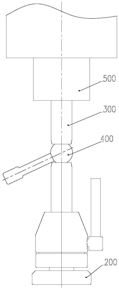
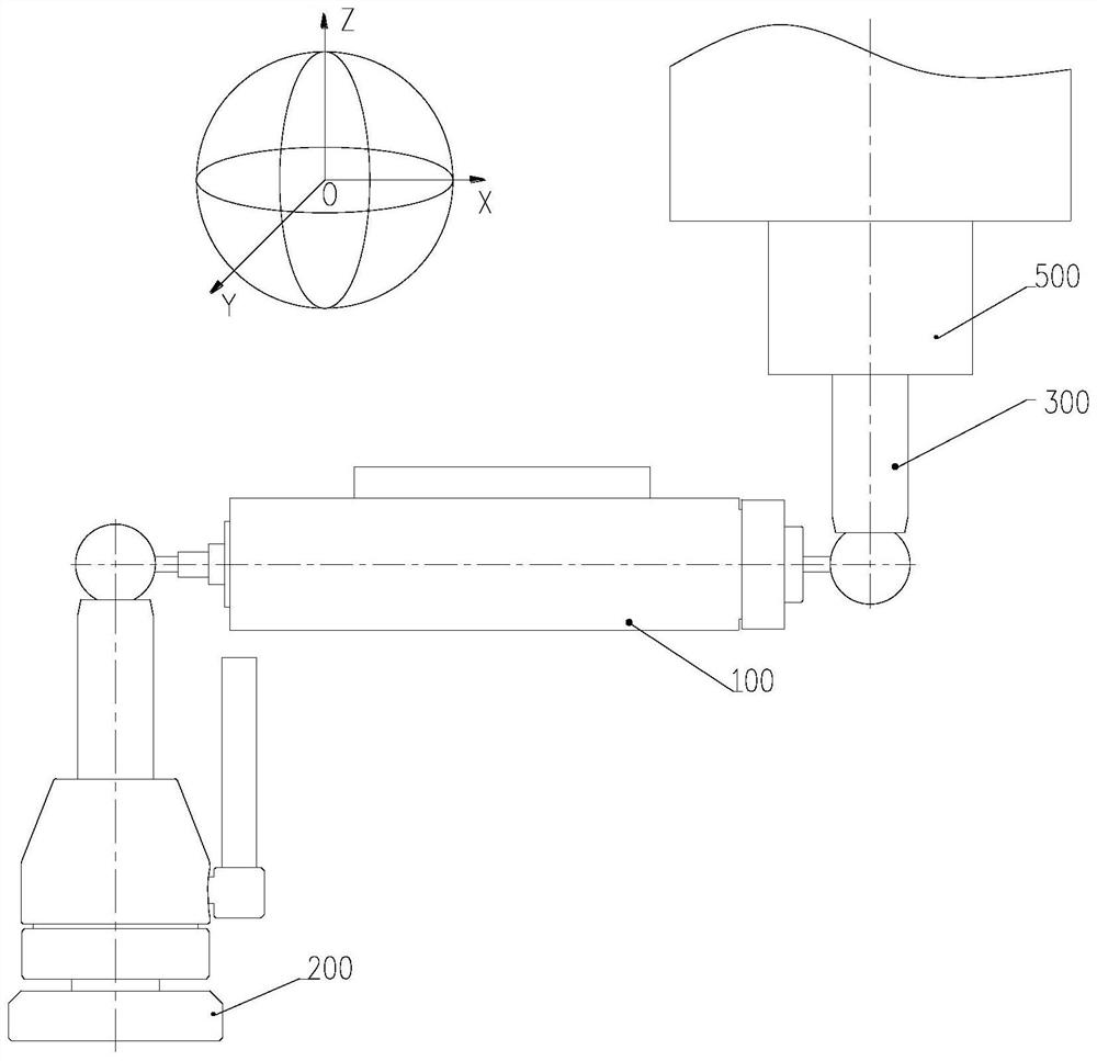
[0045] like figure 1 and figure 2 As shown, an inductive wireless ballbar is mainly composed of four parts: a ballbar host 100 , a center support assembly 200 , a center cup assembly 300 and a setting ball assembly 400 .

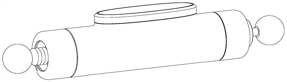
[0046] like Figure 3 to Figure 6 As shown, the ballbar host 100 includes: a first measuring ball 1, a measuring rod 2, a measuring head body 3, a guide sleeve 4, a ballbar body 5, a circuit board cover 6, a circuit board 7, and a magnetic core sleeve rod 8 , Battery positive guide 9, battery 10, battery end cap 11, second measuring ball 12, measuring ball connecting rod 13, shrapnel 14, battery negative shrapnel 15, magnetic core 16, coil 17, return spring 18, pin 19.

[0047] like Figure 7 to Figure 10 As shown, the central support assembly 200 includes: a measuring ball support block 20, a magnet 21, a movable support rod 22, an elastic claw...


PUM


Abstract

The invention provides an inductance type wireless ball rod instrument. The inductance type wireless ball rod instrument is mainly composed of a ball rod instrument main machine, a center support assembly, a center cup assembly and a set ball assembly. The ball rod instrument main machine comprises an inductance measuring head assembly, a battery assembly, a circuit board assembly and a ball rod instrument main body. A wireless measuring system composed of the ball rod instrument main machine, the center support assembly and the center cup assembly is used for comprehensively detecting the precision of a CNC machine tool motion shaft. The instrument is simple to operate, high in precision, low in cost and capable of quickly detecting the precision of the CNC machine tool motion axis.

Description

technical field [0001] The invention relates to the field of error measurement of circular motion track of a numerical control machine tool. Background technique [0002] CNC machine tools play a very important role in modern processing technology. The accuracy of machine tools determines the accuracy of machined parts. If it can be determined that the accuracy of the machine tool meets the requirements of the index before processing the parts, the generation of scrap products can be avoided, thereby avoiding large economic losses. Laser interferometers can be used to detect and compensate the accuracy of machine tool motion axes, but it takes a long time. In actual production, processing workers only need to know whether the accuracy of the machine tool meets the requirements, and it is not necessary to compensate the accuracy of the machine tool. Therefore, it is necessary to have a device for quickly detecting the accuracy of the machine tool. The ballbar is used to co...

Claims


Application Information

Patent Timeline
Patent Type & Authority Applications(China)
IPC IPC(8): G05B19/401B23Q17/00
CPCG05B19/401B23Q17/00G05B2219/37106G05B2219/37457G05B2219/37581
Inventor 黄庭总张和君吴兴发陈源
Owner CHOTEST TECH INC
Why Eureka
Try Eureka