Device and method for detecting water flow of gas tubine cooling blade
A technology for cooling blades and gas turbines, which is applied to the direction of detecting fluid flow and volume/mass flow generated by electromagnetic effects by using electromagnetic flowmeters, and can solve the problems of water flow measurement of turbine cooling blades and the inability to perform gas turbines, etc. The method is simple, Wide versatility and simple device structure
- Summary
- Abstract
- Description
- Claims
- Application Information
AI Technical Summary
Problems solved by technology
Method used
Image


Examples
Embodiment 1
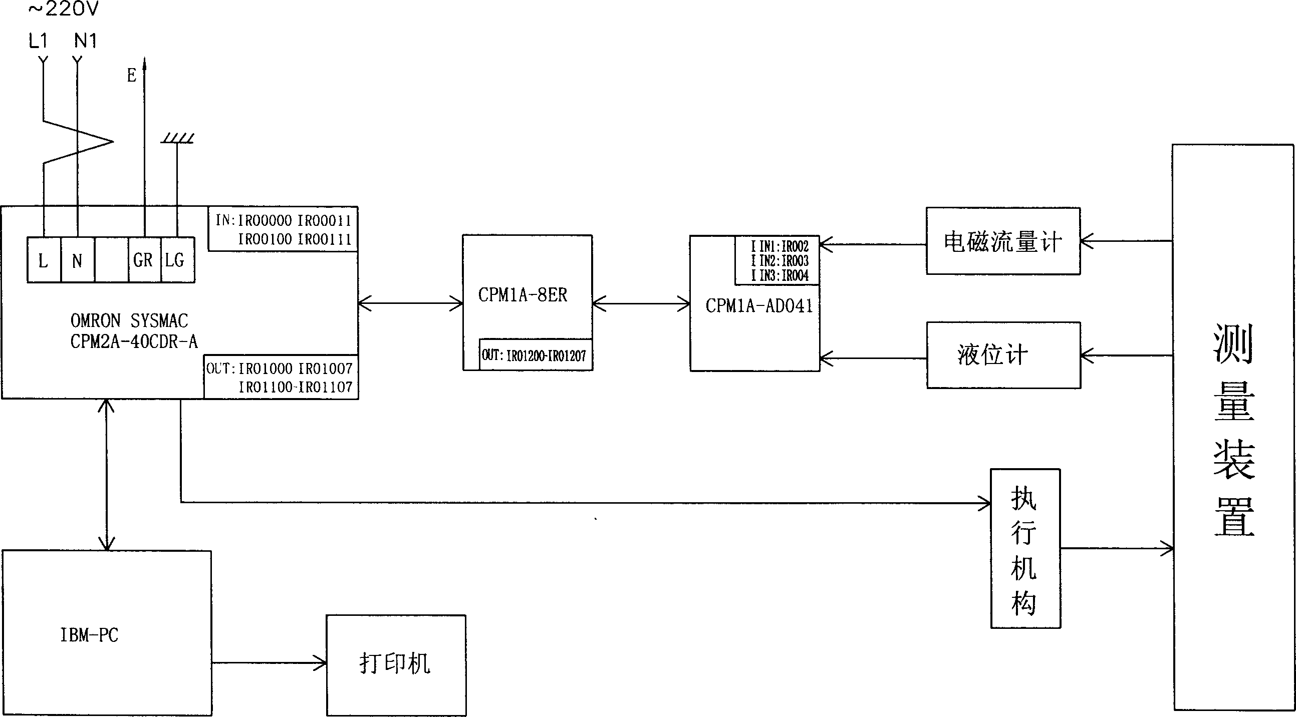
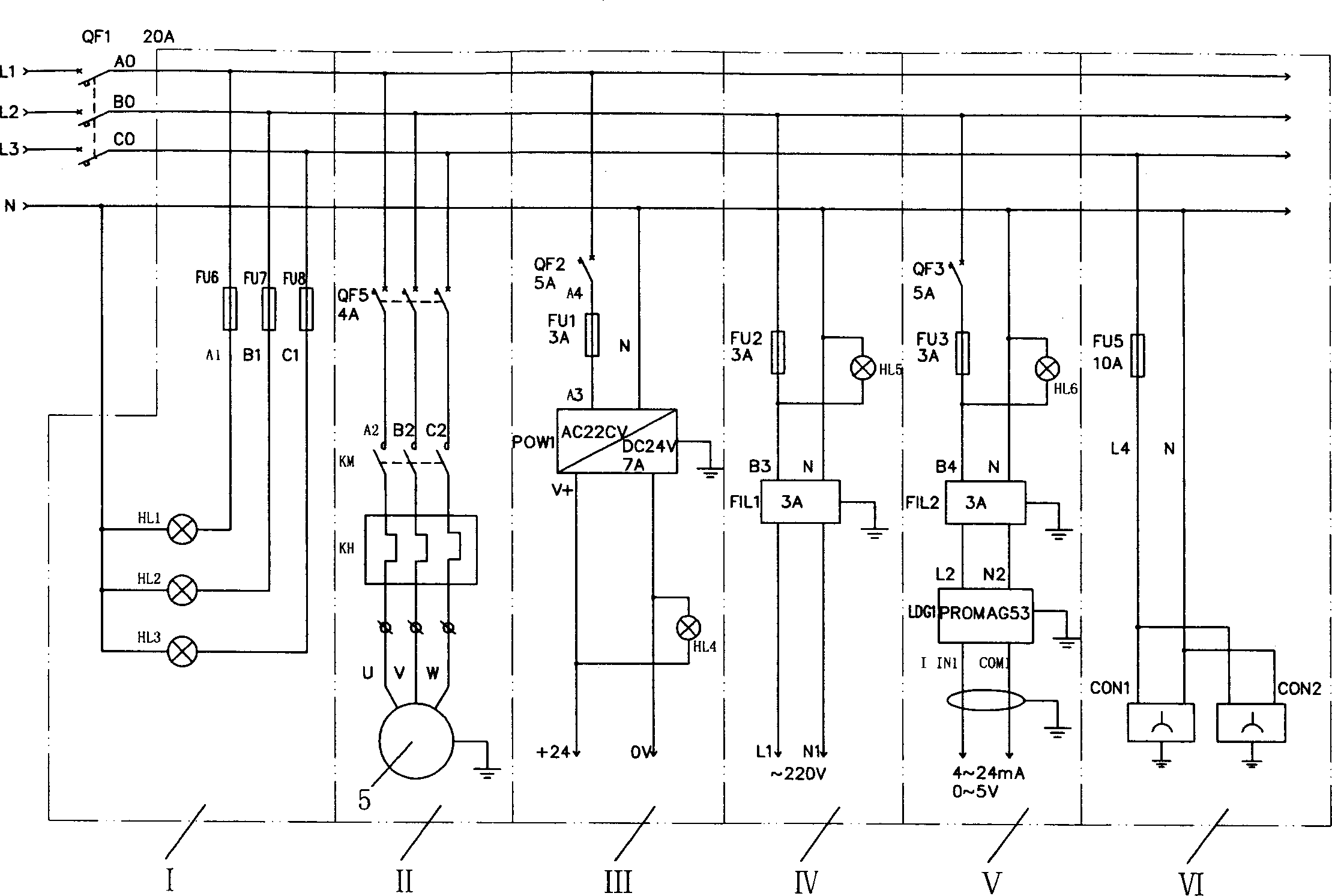
[0050] Embodiment 1: the present invention is as figure 1 As shown, the solenoid valve 6 is a two-position three-way solenoid valve, the electric valve 10 is a two-position two-way electric valve, and one electromagnetic flowmeter. The manufacturer is: Germany E+H, the model is: 53W15-UA0B1, and the diameter is 15mm . The model of the PLC is: CPM2A-40CDR-A, the model of the output module connected to it is: CPM1A-8ER, the model of the A / D converter is: CPM1A-AD041, and the place of manufacture is OMRON in Japan. Its mechanical structure includes lower water tank 1, high-level water tank 16, liquid level gauge 17, workbench 14, electrical control system and main frame. The main frame is fixed around the two water tanks. The pipeline is connected to the lower water tank 1. A liquid level gauge 17 is installed inside the high level water tank 16 and placed above the workbench 14. The liquid level gauge 17 is DC24V for measuring water level. The high level water tank 16 is used f...
Embodiment 2
[0081] Embodiment 2: the present invention is as figure 1 As shown, there are two electromagnetic flowmeters, the manufacturer is: Germany E+H, the model is: 53W25-UAOB1, the diameters are 15mm and 25mm respectively; the solenoid valve 6 is a two-position three-way solenoid valve, the electric valve 10 and the second The electric valve 19 of the electromagnetic flowmeter is a two-position two-way electric valve; the PLC model is: CPM2A-40CDR-A, the output module model connected to it is: CPM1A-8ER, the A / D converter model is: CPM1A-AD041, The place of origin is Japan OMRON. Its mechanical structure includes a lower water tank 1, a high water tank 16, a liquid level gauge 17, a workbench 14, a water inlet device, two water outlet devices, an electrical control system and a main frame. The main frame is fixed around the two water tanks. Above the lower water tank 1, the lower part of which is connected to the lower water tank 1 through pipelines. A liquid level gauge 17 is inst...
PUM
 Abstract
Description
Claims
Application Information
 - R&D
- Intellectual Property
- Life Sciences
- Materials
- Tech Scout
- Unparalleled Data Quality
- Higher Quality Content
- 60% Fewer Hallucinations
Browse by: Latest US Patents, China's latest patents, Technical Efficacy Thesaurus, Application Domain, Technology Topic, Popular Technical Reports.
© 2025 PatSnap. All rights reserved.Legal|Privacy policy|Modern Slavery Act Transparency Statement|Sitemap|About US| Contact US: help@patsnap.com