Temperature detecting and control circuit

A control circuit and controller technology, applied in hardware monitoring, etc., can solve problems such as inaccurate results, easy heat generation, and high cost, and achieve the effects of reducing overall calorific value, taking into account heat dissipation performance, and reducing control costs

Active Publication Date: 2006-11-08
ASUSTEK COMPUTER INC
View PDF0 Cites 9 Cited by
  • Summary
  • Abstract
  • Description
  • Claims
  • Application Information

AI Technical Summary

Problems solved by technology

[0003] The display card in the computer system is easy to generate heat due to the need to process high-speed image calculations
In the past, display cards used temperature detection chips. Although detailed temperature can be measured, the results are generally inaccurate and expensive.
In terms of temperature control, PWM (pulse width modulation) ICs were used to control the speed of fans in the past, but this

Method used


Image

  • Temperature detecting and control circuit
  • Temperature detecting and control circuit
  • Temperature detecting and control circuit

Examples


Embodiment Construction

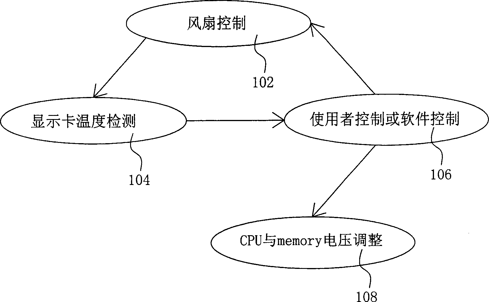
[0026] figure 1 A flow chart example of the operation of the temperature detection and control circuit of the present invention is shown. First, the temperature of a hardware (such as a display card) is detected (step 104). Next, it is determined to allow the user to adjust or utilize an application software (application) to automatically adjust the temperature of the display card (step 106). Next, use the speed of a fan to control the temperature of the graphics card (step 102 ) or adjust the voltage of a graphics processing unit (GPU) and memory (step 108 ).

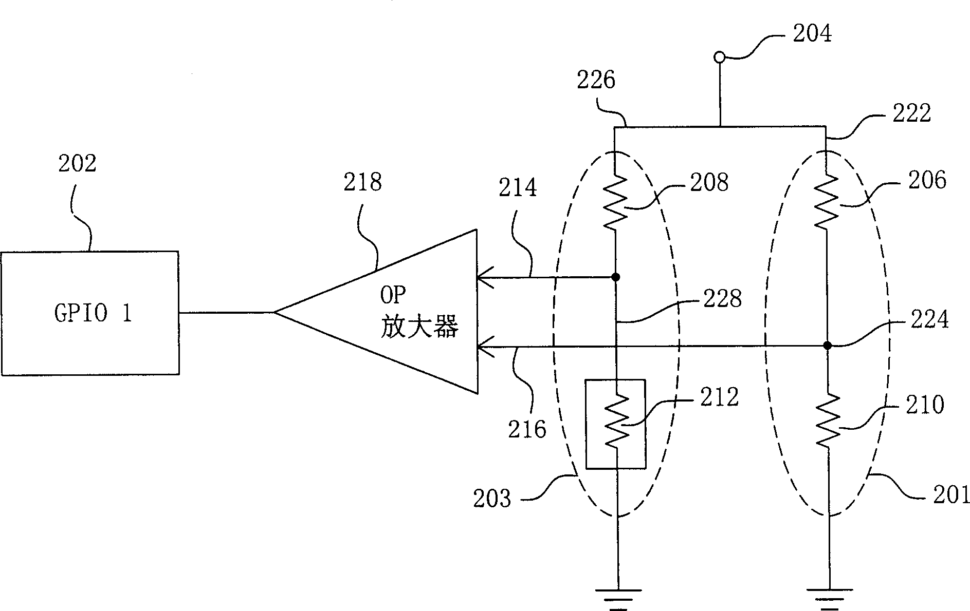
[0027] figure 2 A circuit diagram of an embodiment of a temperature detection circuit is shown. The first voltage dividing circuit 201 receives a power source 204 and outputs a first voltage 216 . The second voltage dividing circuit 203 receives the power source 204 and outputs a second voltage 214 . The second voltage dividing circuit 203 has a temperature sensing electronic element 212 for detecting the tempera...


PUM


Abstract

This invention provides a temperature test and control circuit including a first bleeder circuit, a second bleeder circuit, a fan rotation speed controller and a comparing circuit, in which, the first bleeder circuit outputs a first voltage, the second bleeder circuit outputs a second voltage and has a temperature-sensing electronic element to test the temperature of a piece of hardware, the comparing circuit receives and compares the two voltages and outputs the result to the fan rotation speed controller, which maintains a first speed when receiving a first control signal and maintains a second rotation speed when receiving a second control signal.

Description

technical field [0001] The present invention relates to a temperature detection and control circuit, and in particular to a temperature detection and control circuit for a computer system. Background technique [0002] Today's computer systems are getting smaller and smaller, but the computing speed is getting faster and faster. Many components will emit heat under high-speed computing, which will reduce the performance of the computer system and even damage the system. Therefore, how to dissipate heat from a computer system is a very important issue. [0003] The display card in the computer system is easy to generate heat because it needs to process high-speed image calculations. In the past, display cards used temperature detection chips. Although detailed temperature measurements can be made, the results are often inaccurate and expensive. In terms of temperature control, in the past, PWM (pulse width modulation) IC was used to control the speed of the fan, but this m...

Claims


Application Information

Patent Timeline
IPC IPC(8): G06F11/30
Inventor 张建隆高国忠
Owner ASUSTEK COMPUTER INC
Why Eureka
Try Eureka