Magnetic field focus coil array used for conductivity imaging and functional magnetic stimulation
A coil array and magnetic field focusing technology, which is applied in the direction of using the magnetic field generated by the coil, material analysis and application through electromagnetic means, can solve the problem that the calculation area of the imaging algorithm is large, it is not suitable for high-resolution imaging, and the secondary magnetic field of the signal Difficult detection and other problems, to achieve the effect of small focus area, reduced imaging calculation area, and small magnetic field distribution area
- Summary
- Abstract
- Description
- Claims
- Application Information
AI Technical Summary
Problems solved by technology
Method used
Image

Examples
Embodiment 1
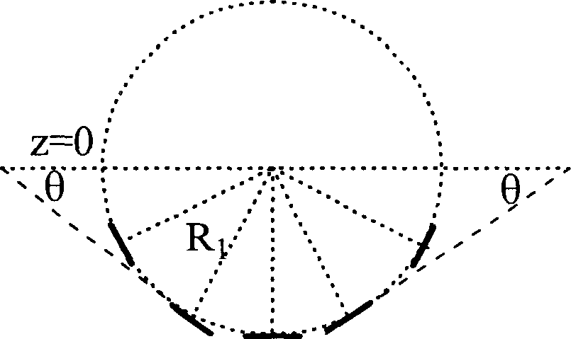
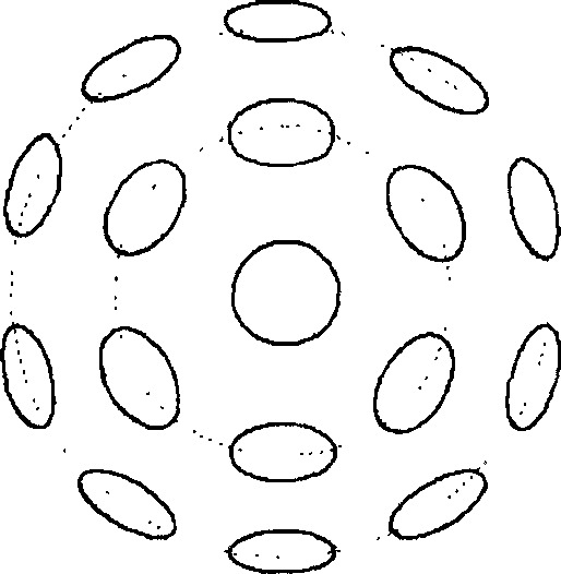
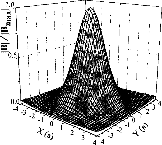
[0050] The structure of Embodiment 1 is that a plurality of coils are arranged in a hemispherical structure, which is called a hemispherical array of coils, as shown in FIG. 1 a . The design uses a total of 17 unit coils, which are divided into 3 layers, each layer has 1, 6, and 10 coils, and the angle between each layer of coils and the straight line z=0 is θ. The radius of the ball is R 1 , the coil plane and the sphere are tangent to the geometric center of each unit coil, such as Figure 1a-1 , 1a-2 shown. When the excitation current of the first layer coil is 11.125A, θ=0°; the excitation current of the second layer coil is -8.125A, the negative sign indicates the current reverse, θ=36.6°; the excitation current of the third layer coil is 3.125 A, θ=66.1°; the magnetic field distribution generated by the array is as follows Figure 1b-1 and 1b-2It can be seen from the figure that the magnetic field distribution of the coil array can achieve focusing, and the focusing ...
Embodiment 2
[0051] The structure of embodiment 2 is that multiple coils are arranged on spherical surfaces with different radii, and the inclination angles of the coils on the spherical surfaces with different radii are different, but all the coils are coplanar at the edge close to the direction of the biological tissue to be measured, which is called a multilayer coplanar coil array. . The design uses a total of 19 coils, as shown in Figure 2a, which are divided into 4 layers, each layer has 1, 4, 6, and 8 coils, and the sphere radius of the coils in each layer is gradually increasing, and the sphere radius of the center coil is the smallest. ,Such as Figure 2a-1 , 2a-2 As shown, the coil planes of each layer are tangent to the respective spherical surfaces at the geometric center of the unit coil. When the excitation current of the first layer coil is 13.25A, θ=0°, the excitation current of the second layer coil is 2.625A, θ=39.0°, and the excitation current of the third layer coil i...
Embodiment 3
[0052] The structure of embodiment 3 is that the centers of multiple coils are evenly distributed on the same circle, and the plane of the unit coil is perpendicular to the plane of the circle to form a circular coil array. The radius of the ring is equal to the radius of the unit coil, as Figure 3a-1 , 3a-2 shown. When the current distribution on the coil is: -14.50A, 8.875A, 8.625A, 12.125A, 12.25A, -5.375A, 15.625A, -1.000A, -10.125A, 5.000A, 8.250A, 9.125A, 14.125A A, 4.750A, -1.750A, 14.500A, 4.000A, 14.625A, 7.750A, 7.500A, the magnetic field distribution of the coil array is shown in Figure 3b. It can be seen from the figure that the focal area of the array is smaller and smaller than the aperture of a single coil. The focus effect is the best, and it can achieve the focus of two areas that are close to each other, see Figure 3c-1 and 3c-2 shown.
PUM
 Abstract
Description
Claims
Application Information