
Layer spreading design calculating method of composite material according to rigidity requirement

A composite material and composite material board technology, which is used in aircraft parts, ground installations, transportation and packaging, etc., can solve the problem that the rigidity requirement is more difficult to meet than the strength requirement.

Inactive Publication Date: 2006-11-29
BEIHANG UNIV
View PDF0 Cites 19 Cited by
  • Summary
  • Abstract
  • Description
  • Claims
  • Application Information

AI Technical Summary

Problems solved by technology

Especially for high-speed fighters, the stiffness requirements are often more difficult to meet than the strength requirements

Method used


Image

  • Layer spreading design calculating method of composite material according to rigidity requirement
  • Layer spreading design calculating method of composite material according to rigidity requirement
  • Layer spreading design calculating method of composite material according to rigidity requirement

Examples


Embodiment Construction

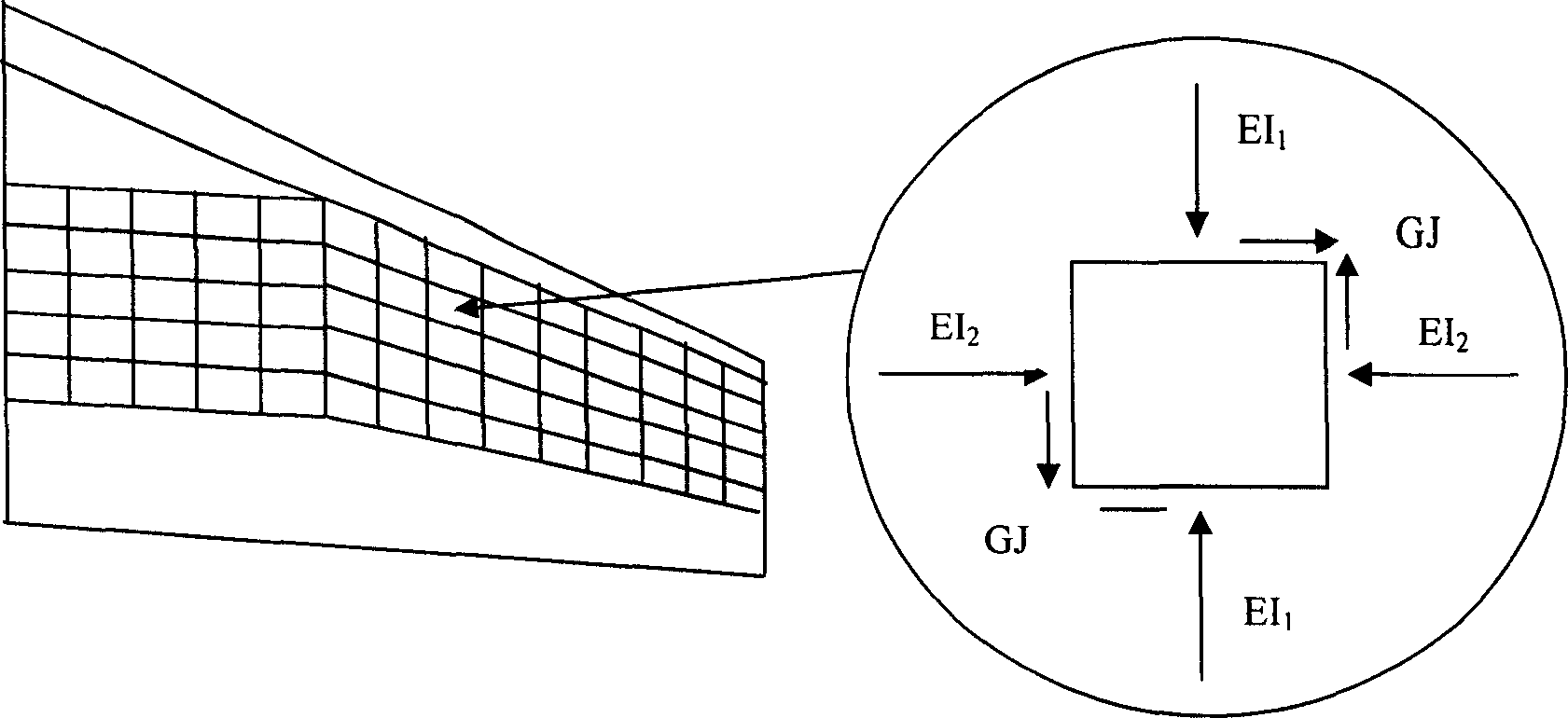
[0171] Step 1: Simplify the airfoil as an engineering beam in the calculation of aeroelasticity

[0172] After the airfoil is simplified into an engineering beam, according to the aeroelastic calculation results of the airfoil, the required distribution curves of bending stiffness EI1 and torsional stiffness GJ of each section along the axis are proposed. In this way, on the premise of meeting the strength requirements in the structural design, the stiffness requirements should also be met.

[0173] Step 2: Composite laminate lay-up design meeting the two-way stiffness requirements:

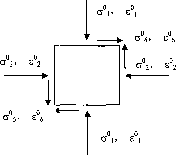
[0174] We obtained from the derivation of the first part, when the aeroelastic calculation of the airfoil is carried out by the engineering beam, the bending stiffness EI1 and the torsional stiffness GJ of the airfoil along the span direction are given. After the transformation of formulas (2) and (6), the two-way stiffness requirements of the skin on each cut surface can be given, that is, the ...


PUM


Abstract

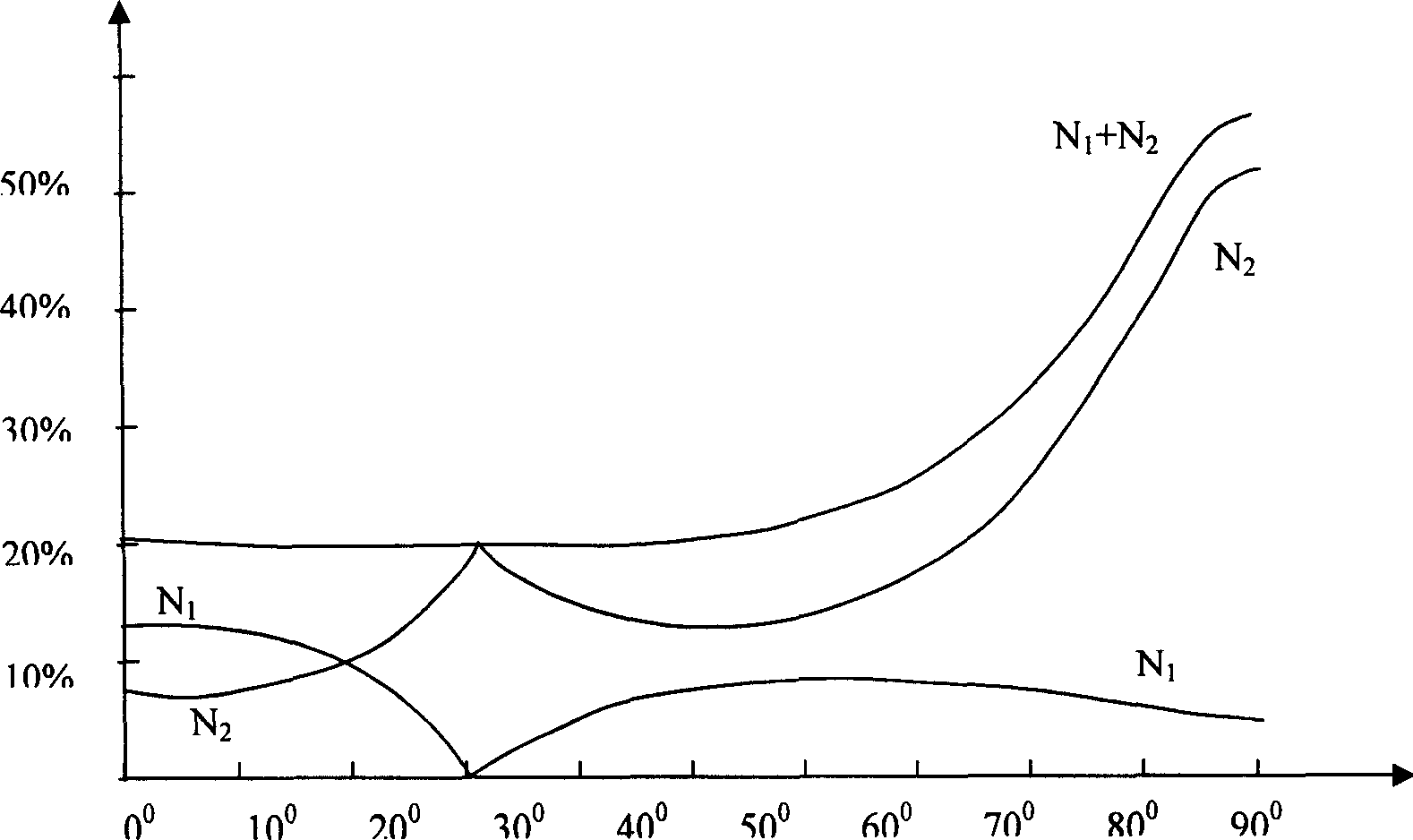
A design calculation method based on the rigidity requirement for laminated composite material, such as the vertical tail fin of airplane features that when the relative angle between layers of a laminated plate with equal rigidity in three directions is changed, its thickness or weight characteristic is not changed, and the relation between the rigidity in three directions and the relative weight is used in the aerodynamic elasticity calculation to replace complex calculation model.

Description

Technical field: [0001] The invention relates to the design of aircraft structural parts, especially the design method of composite material layup. Background technique: [0002] In the design of the airfoil structure, in addition to meeting the strength requirements, the stiffness index proposed by the aeroelastic calculation must also be met. Especially for high-speed fighters, the stiffness requirements are often more difficult to meet than the strength requirements. One of the characteristics of composite materials superior to metal materials is that its axial stiffness and shear stiffness can be designed separately, so we can use this feature to design a lighter and more reasonable airfoil than metal structures. In order to carry out the layup design according to the stiffness requirement, the research of this topic is put forward. [0003] In the calculation of aeroelasticity, the stiffness requirements of the airfoil structure are often given in the following two fo...

Claims


Application Information

Patent Timeline
Patent Type & Authority Applications(China)
IPC IPC(8): B64F5/00
Inventor 崔德刚
Owner BEIHANG UNIV
Learn More