

Combined garbage transit station
A transfer station and combined technology, which is applied in the direction of garbage transmission, garbage collection, transportation and packaging, etc., can solve the problems of loose garbage, high water content, and high cost of garbage stations
- Summary
- Abstract
- Description
- Claims
- Application Information
AI Technical Summary
Problems solved by technology
Method used
Image

Examples
Embodiment Construction
[0012] Below in conjunction with accompanying drawing, the present invention is further described.
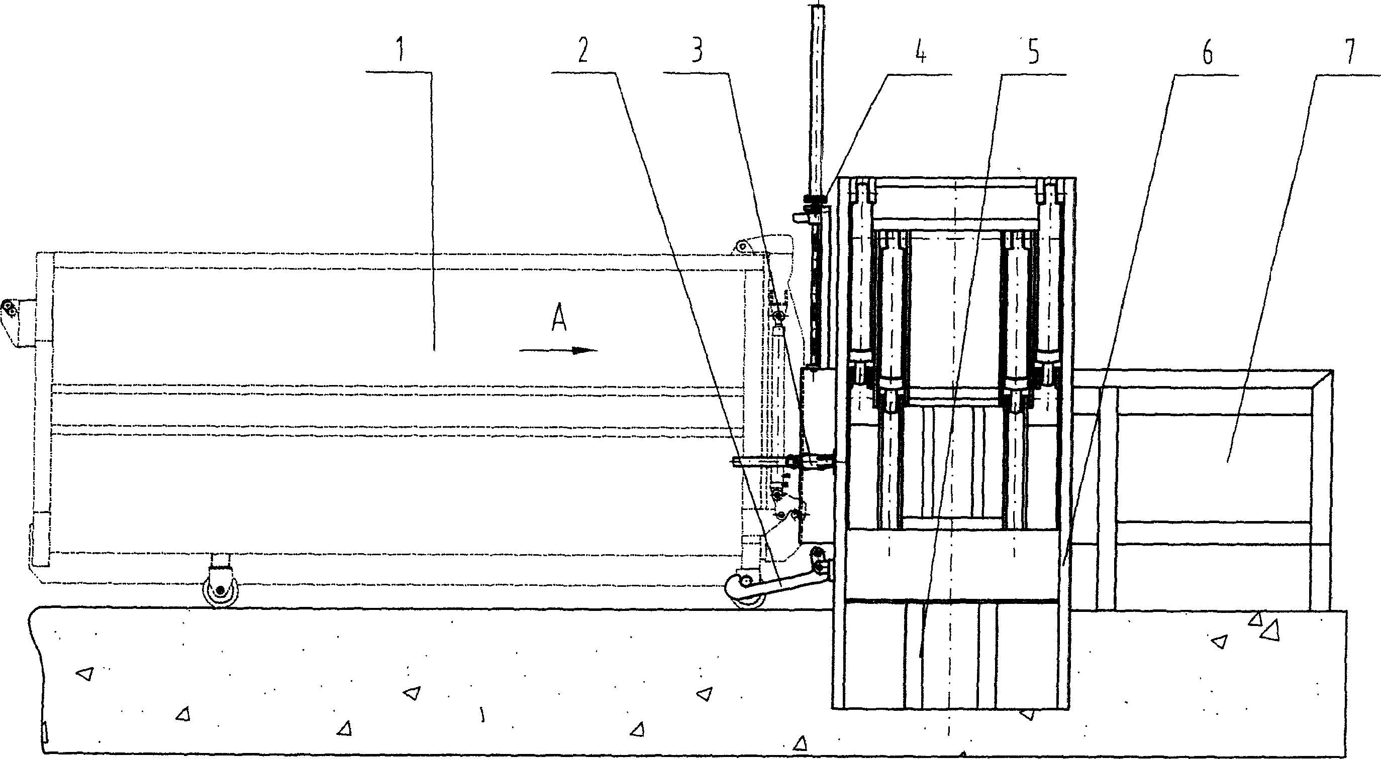
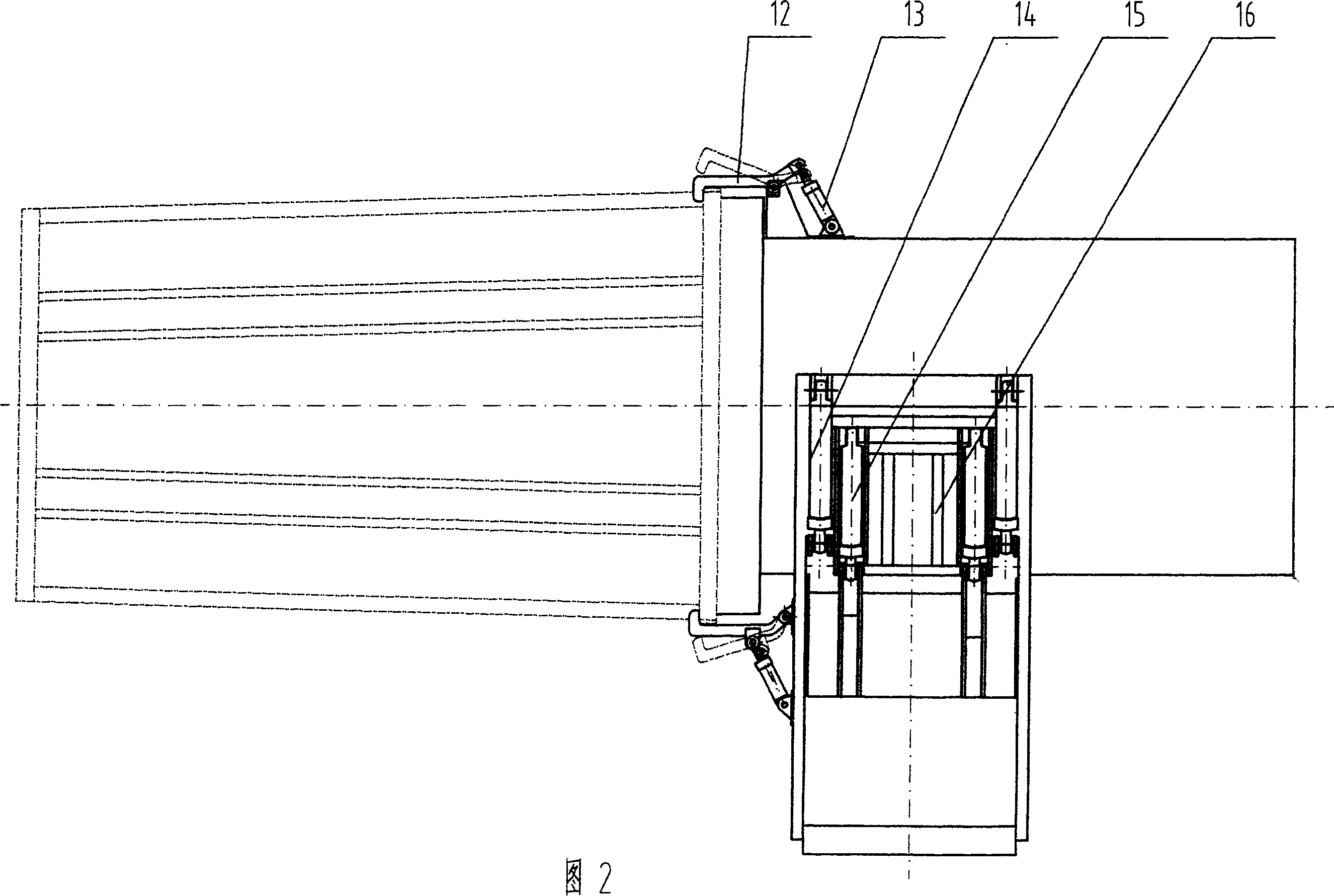
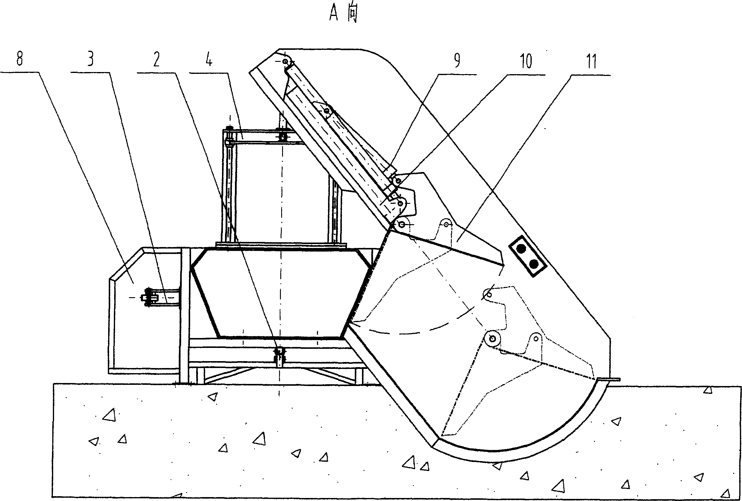
[0013] Such as figure 1 , 2, and 3, the present invention includes a garbage truck compartment 1, a box-moving mechanism 2, a locking hook assembly 3, a main gate 4, a combination box body 5, and a hydraulic system 8, and the garbage truck compartment 1 is placed in a garbage station, and the box-moving mechanism 2 is installed At the bottom of the combined box body 5, the garbage car 1 is connected with the combined box body 5 through the lock hook assembly 3, and the main gate 4 is housed between them, and the hydraulic system is installed and fixed on the ground.
[0014] The locking hook assembly 3 of the present invention is composed of a locking hook 12 and a locking hook oil cylinder 13, and the locking hook 12 and the locking hook oil cylinder 13 are connected by pin shafts and fastened to the left and right sides of the combined box body 5.
[0015] The combined box 5...
PUM
 Abstract
Description
Claims
Application Information