Facilities equipment communication circuit

A communication circuit and machine technology, applied in the field of data communication, can solve the problems of circuit damage, slow circuit response, and inability to achieve high-speed transmission, and achieve the effect of preventing circuit damage and high-speed data transmission.

Inactive Publication Date: 2006-11-29
PANASONIC CORP
View PDF1 Cites 12 Cited by
  • Summary
  • Abstract
  • Description
  • Claims
  • Application Information

AI Technical Summary

Problems solved by technology

That is, in order to prevent the circuit from being destroyed when the wiring is wrong, a resistor is inserted into the communication line. Therefore, if the wiring is long, the response of the circuit will change due to the time constant determined by the parasitic capacitance between the lines and the resistance for protection. slow, making high-speed transmission impossible
[0008] In addition, there is another issue that, due to the Figure 8 case, the communication line and the power line are independent of each other, so at least 4 lines are required

Method used


Image

  • Facilities equipment communication circuit
  • Facilities equipment communication circuit
  • Facilities equipment communication circuit

Examples


Embodiment approach 1

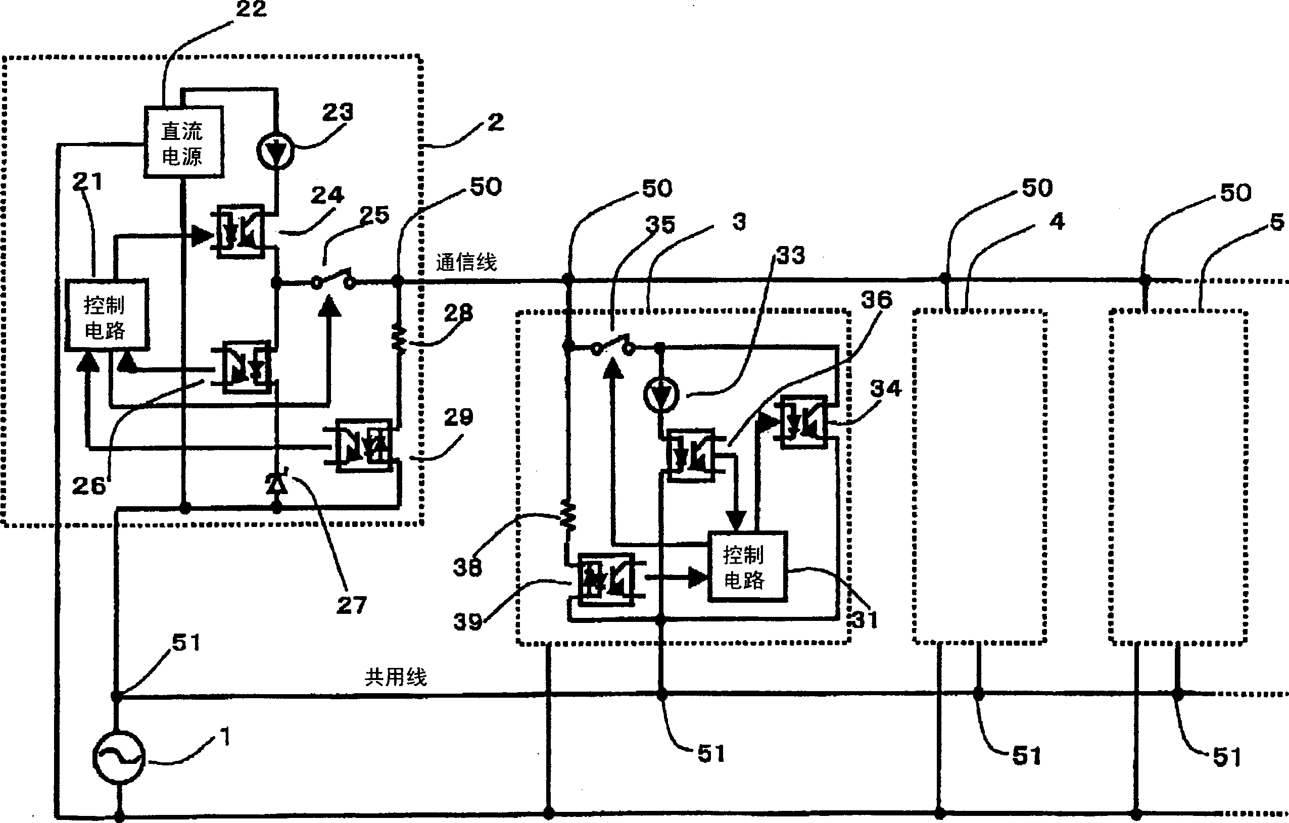
[0076] exist figure 1 Among them, the circuit block 2 is the circuit of the central office, and the circuit blocks 3, 4, and 5 are the circuits of the branch offices. In the central office circuit, a DC power supply 22 generates a DC power supply based on power obtained from the AC power supply 1 for driving the entire machine. From the positive side of the DC power supply 22, the constant current circuit 23, the secondary side of the photocoupler 24 for transmission, the primary side of the photocoupler 26 for reception, and the voltage stabilizing circuit 27 are connected in series to the negative side of the DC power supply 22. The photocoupler 24 for transmission constitutes a switching element, and the photocoupler 26 for reception constitutes a current detection device. By making the negative side of the DC power supply 22 and one end of the AC power supply 1 on the same line, including the power supply, three lines can be used to realize the circuit leading to the sub...

Embodiment approach 2

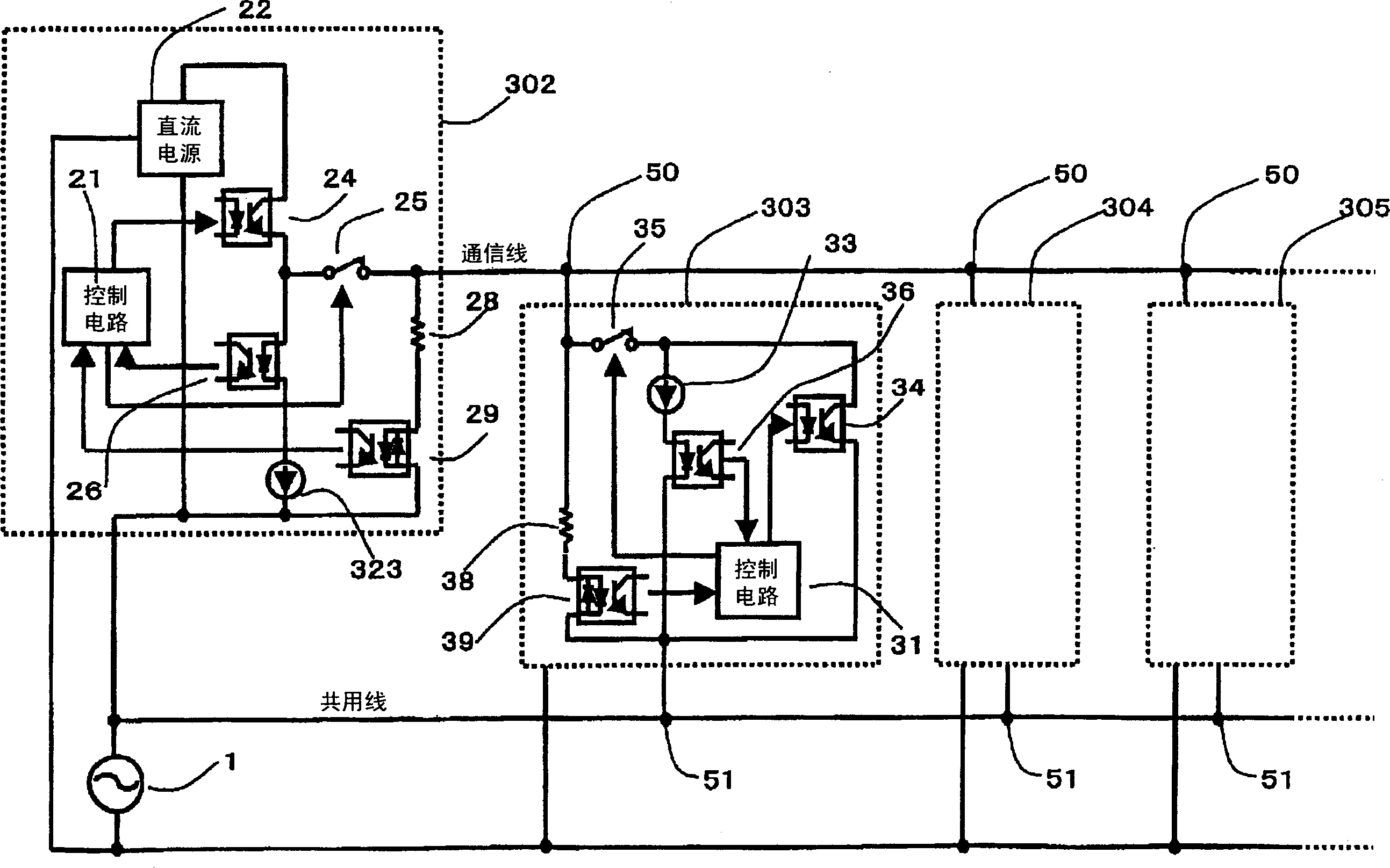
[0087] figure 2 It is a circuit diagram showing the second embodiment. exist figure 2 In the embodiment 1, the circuit structure of the main office 302 is different. From the positive side of the DC power supply 22 in the central office 22, the secondary side of the photocoupler 24 for transmission, the primary side of the photocoupler 26 for reception, and the constant current circuit 323 are connected in series to the negative side of the DC power supply 22.

[0088]Furthermore, according to the present embodiment, the voltage stabilizing circuit 27 in the first embodiment can be omitted. The transmission and reception in the control circuits 21 and 31 and the control method of the relays are the same as those in the first embodiment. The current flowing in the communication line is the total value of the constant current circuits in the main office 302 and the branch offices 303 , 304 , and 305 .

[0089] In addition, in the central office 302, the same effect can be ...

Embodiment approach 3

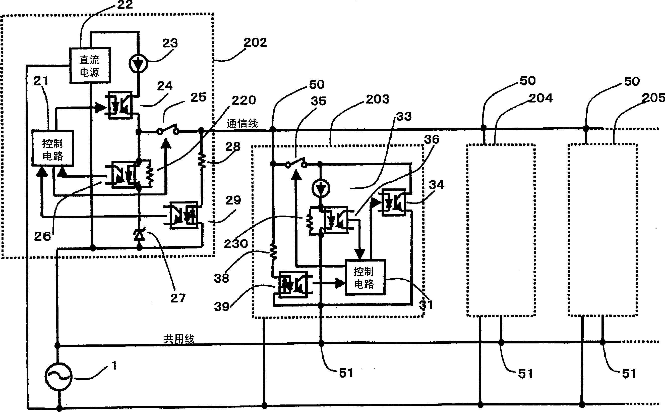
[0091] image 3 It is a circuit diagram showing the third embodiment. image 3 The difference between the circuit shown in Embodiment 1 and the circuit shown in Embodiment 1 is that resistors 220 and 230 for promoting discharge are connected in parallel to the primary sides of photocouplers 26 and 36 for reception. Accordingly, when the current of the communication line is cut off, the charge stored in the parasitic capacitance and the like can be quickly discharged, so that the communication speed can be further increased.


PUM


Abstract

A communication circuit is realized which uses three wires, including a power supply, to provide an erroneous-connection protection, a long wiring, and a high-rate transmission. In a communication system using, as a shared wire, one of two AC power supply wires, a first constant current source is series connected, in a master station, with a master station transmission photo-coupler, a reception photo-coupler and a constant voltage diode in the named order from the positive side of the power supply to the negative side thereof serving as a reference, and a communication path, which extends from a node located between the transmission and reception photo-couplers, is wired through a relay to slave stations. In each of the slave stations, a circuit, in which a second constant current source and a slave station reception photo-coupler are series connected with a reference wire, is parallel connected, via a relay, with a photo-coupler so disposed as to short-circuit an output of the relay to the reference wire. The relay is controllably turned on when it is determined that a potential difference between the communication path and the reference wire becomes below a predetermined value.

Description

technical field [0001] The present invention relates to a data communication circuit between main components of an air conditioner and other residential equipment, for example, relates to data communication between an outdoor unit of a split type air conditioner and a plurality of indoor units. In particular, it relates to circuits that can reduce the number of wires and enable high-speed communication even when the communication wires are long. Background technique [0002] Such as Figure 7 As shown, in the past, the communication between the indoor unit and the outdoor unit of the air conditioner used three wiring lines, two of which were AC power, and the remaining one was a communication line, and the reference power for communication was shared with one of the AC power ( For example, refer to Patent Document 1). [0003] In this method, data is transmitted and received through one communication line, and the LEDs on the primary side of the receiving photocouplers 526 ...

Claims


Application Information

Patent Timeline
IPC IPC(8): H04B3/02H02H11/00H04B3/54
CPCH04B3/542H04B2203/547
Inventor 土山吉朗武田芳彦
Owner PANASONIC CORP
Why Eureka
Try Eureka