Device for adjusting and measuring optical module

A technology for commissioning devices and optical modules, applied to transmission monitoring/testing/fault measurement systems, electrical components, electromagnetic wave transmission systems, etc., can solve problems such as time-consuming, low production efficiency, and high cost of functional single boards, and achieve The effect of reducing manual operations, improving production efficiency, and reducing skill requirements

Active Publication Date: 2006-12-06
GLOBAL INNOVATION AGGREGATORS LLC
View PDF0 Cites 13 Cited by
  • Summary
  • Abstract
  • Description
  • Claims
  • Application Information

AI Technical Summary

Problems solved by technology

[0015] figure 1 The described method takes a lot of time to collect data, which is not conducive to improving production efficiency and reducing production costs
In addition, in the process of manually collecting and recording data, it is easy to make mistakes, resulting in inaccurate fitting coefficients
[0016] The method of using functional single boards for optical module

Method used


Image

  • Device for adjusting and measuring optical module
  • Device for adjusting and measuring optical module
  • Device for adjusting and measuring optical module

Examples


Example Embodiment

[0062] The core technical content of the present invention is to realize digital adjustment and testing of optical modules of various speeds, and realize a certain degree of automated production.

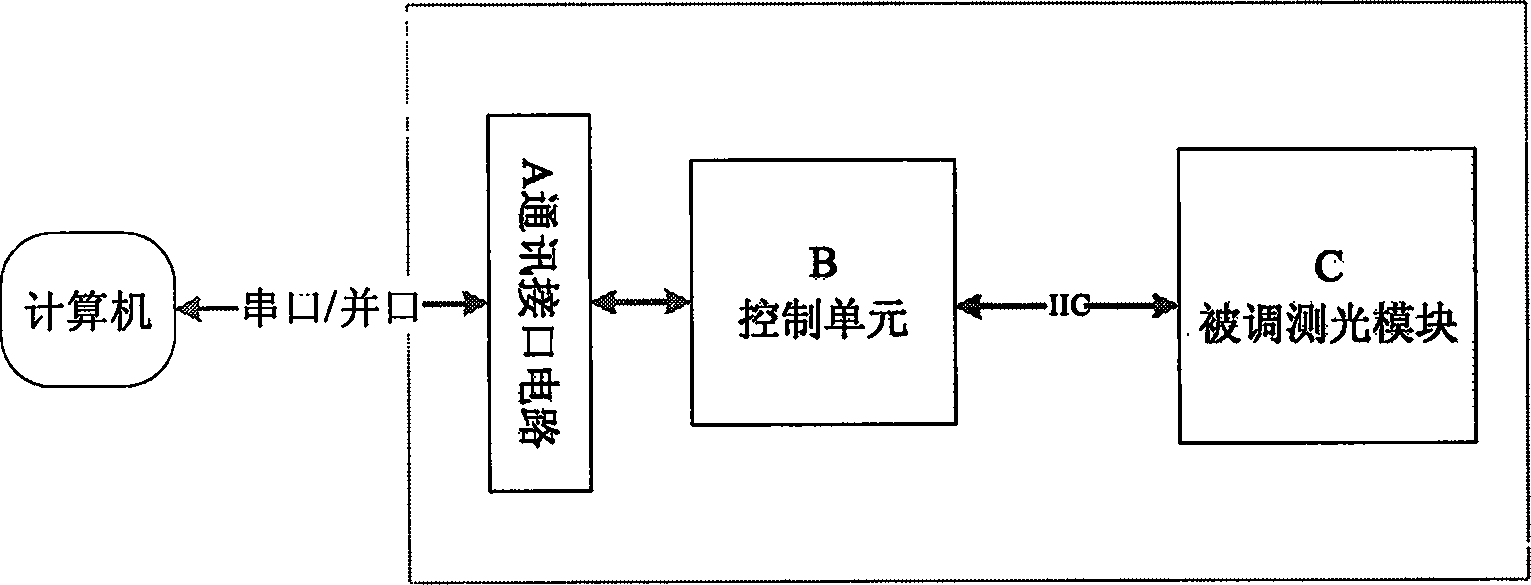
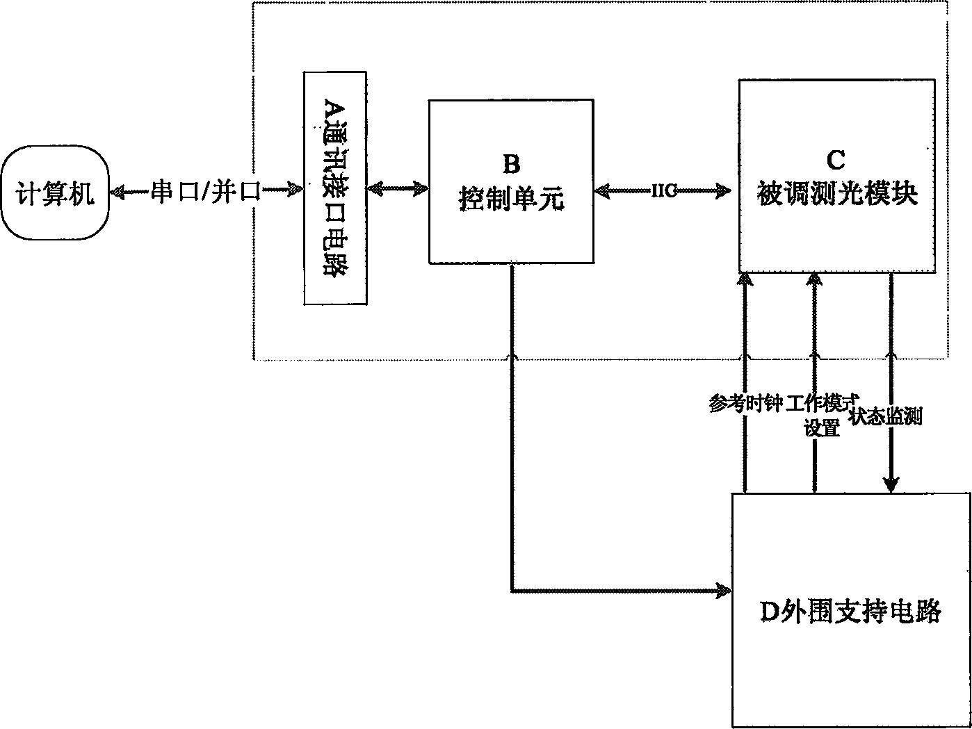
[0063] The basic components of the optical module debugging device of the present invention include: a communication interface circuit and a control unit, such as figure 2 As shown in A and B. The connection relationship between the optical module commissioning device and the computer and the optical module to be commissioned is as follows: figure 2 As shown in the figure, C is the optical module to be tested.

[0064] When commissioning the optical module, the operator sets the commissioning options through the commissioning interface on the computer and issues commissioning commands. The commissioning command issued is transmitted to A (communication interface circuit) through the serial port. The communication interface circuit transforms the received signal, transforms it into a s...


PUM


Abstract

The invention includes parts and operations: an optical module to be adjusted and measured carries out operations corresponding to received specific operation instruction; a computer in use for sending signal of adjusting and measuring instructions to the optical module to be adjusted and measured; a communication interface circuit for converting received signal of adjusting and measuring instructions to adjusting and measuring signals receivable by control unit, and sending the signals to the control unit; being composed of microprocessor and inner peripheral equipment, a control unit processes and interprets the received signals in order to create details operation instructions, which are sent to the optical module to be adjusted and measured through IIC bus. The invention implements debugging performance and calibrating monitored parameter automatically. Features are: debugging multiform optical modules supported, raised production efficiency and lowered cost.

Description

technical field [0001] The invention relates to an optical module commissioning device, which belongs to the technical field of digital optical fiber transmission systems. The invention can cooperate with other instruments to realize efficient commissioning of optical modules, and is suitable for research and development in digital optical fiber communication systems or digital optical fiber networks. production process. Background technique [0002] A large number of optical modules are used in the field of optical communication. With the rapid development of technology in the field of optical communication, higher requirements are put forward for optical modules in optical communication systems, and new types of optical modules emerge as the times require. [0003] These optical modules can not only be adjusted digitally, but also provide monitoring information about the optical modules. For example, received optical power, transmitted optical power, laser bias current, e...

Claims


Application Information

Patent Timeline
IPC IPC(8): H04B10/08H04B10/12H04B10/07
Inventor 华锋许昌武易鸿
Owner GLOBAL INNOVATION AGGREGATORS LLC
Why Eureka
Try Eureka