
Turning device for conveyor

A conveyor and moving direction technology, applied in conveyors, transportation and packaging, escalators, etc., can solve problems such as pallet congestion, damage, unsatisfactory track characteristics and mechanism wear, and achieve the effect of simple structure and reliable operation

Inactive Publication Date: 2006-12-06
KONE CORP
View PDF1 Cites 18 Cited by
  • Summary
  • Abstract
  • Description
  • Claims
  • Application Information

AI Technical Summary

Problems solved by technology

However, this solution disclosed in the GB patent specification involves the problem that the track has a so-called dead point at an end point where the pallet position is not completely precisely defined
As a result, the pallets can cause jams at dead spots, causing the entire unit to stop due to operational failure and possibly even be damaged
The risk of congestion increases due to running gaps, suboptimal track characteristics and wear on mechanisms

Method used


Image

  • Turning device for conveyor
  • Turning device for conveyor
  • Turning device for conveyor

Examples


Embodiment Construction

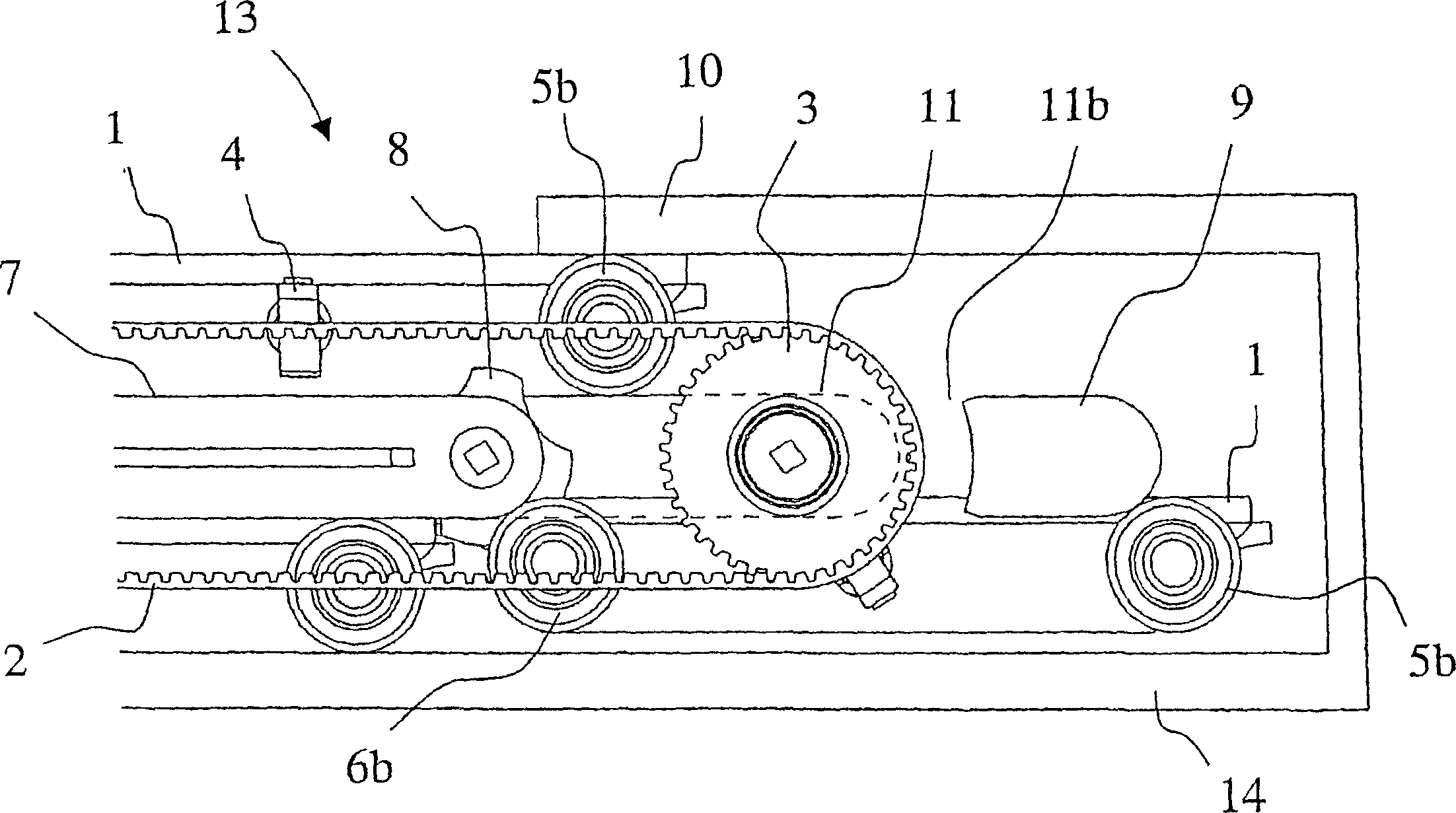
[0015] The conveyor structure 13 of the present invention includes a frame structure 14 whose function is to hold equipment together and transmit forces to the base beneath it. Inside the frame structure is the pallet track on which passengers stand on the upper surface. In addition, the conveyor structure comprises at least one pallet track drive machine and handrails and its drive machine, wherein the pallet track drive machine comprises a drive toothed pulley 3 and a toothed belt 2 .

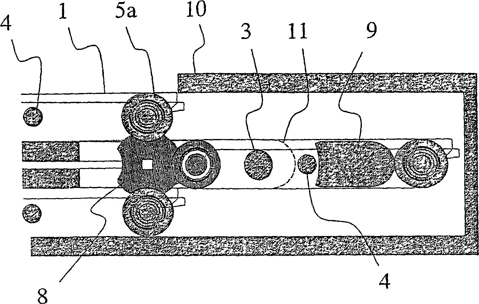
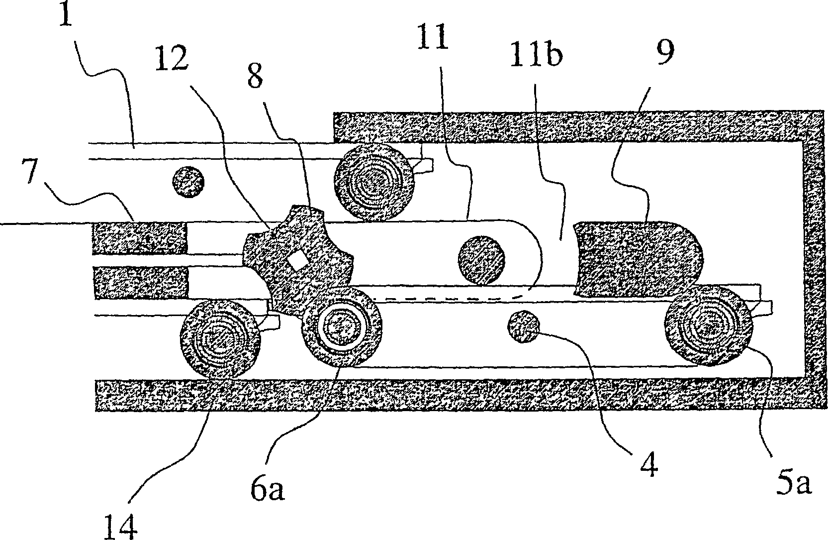
[0016] The pallet track consists of a separate pallet 1 provided with wheels, the front wheels 5a and 5b are placed at the front corners of the pallet with respect to the normal conveying direction of the conveyor, and the rear wheels 6a and 6b are placed at the corners of the pallet. rear corner. The front wheels 5a are placed at a distance outwards at the front corners with respect to the corresponding rear wheels 6a on the same side of the pallet. Likewise, the rear wheels 6b on the othe...


PUM


Abstract

The invention concerns a method and an apparatus for changing the direction of motion of a pallet (1) moving on wheels (5a, 5b, 6a, 6b) at the end of a transport conveyor or equivalent, in which transport conveyor the pallets moving in the direction of travel move on a different level than the pallets moving in the return direction, and in which method the direction of motion of the pallet (1) is changed keeping the pallet in substantially the same attitude throughout the direction changing phase. During direction change, the trailing end of the pallet (1) in the direction of travel is guided by positive control from the level of the traveling direction to the other level.

Description

technical field [0001] The invention relates to a method as defined in the preamble of claim 1 and a device as defined in the preamble of claim 5, wherein said device is used to vary the position of the pallet at the end of the conveyor or equivalent. direction of movement. Background technique [0002] Like escalators, conveyors are conveying equipment designed to move people or goods. It is different from an escalator in that it always runs along a roughly horizontal position or along a slightly inclined position relative to its direction of movement (as usually inclined by 1-15°), therefore, continuous steps, that is, multiple The pallets form a generally even and linear track, rather than forming stepped steps like an escalator. Instead of successive steps, the conveyor device can also have a continuous conveyor belt, in which case the conveyor device is similar to a belt conveyor. The conveying device can also be called a moving walkway or a moving walkway. [0003]...

Claims


Application Information

Patent Timeline
Patent Type & Authority Applications(China)
IPC IPC(8): B66B21/02B66B21/10B65G17/18B66B23/14
CPCB66B23/147B65G17/18B65G17/123B66B21/02B66B21/10B65G17/16
Inventor 乔马·穆斯塔拉蒂埃斯科·奥兰科
Owner KONE CORP
Learn More