Centralised lubrication of large diesel engines

A diesel engine, centralized lubrication technology, used in engine lubrication, lubrication of engines with crankcase compressed fuel-air mixture, engine components, etc.

Inactive Publication Date: 2006-12-06
HANS JENSEN LUBRICATORS
View PDF0 Cites 2 Cited by
  • Summary
  • Abstract
  • Description
  • Claims
  • Application Information

AI Technical Summary

Problems solved by technology

[0009] In the case of a mechanical connection, there is a limit to the possibility for the user to control the injection time only for synchronous lubrication that is timed according to the rotation of the crankshaft

Method used


Image

  • Centralised lubrication of large diesel engines
  • Centralised lubrication of large diesel engines
  • Centralised lubrication of large diesel engines

Examples


Embodiment Construction

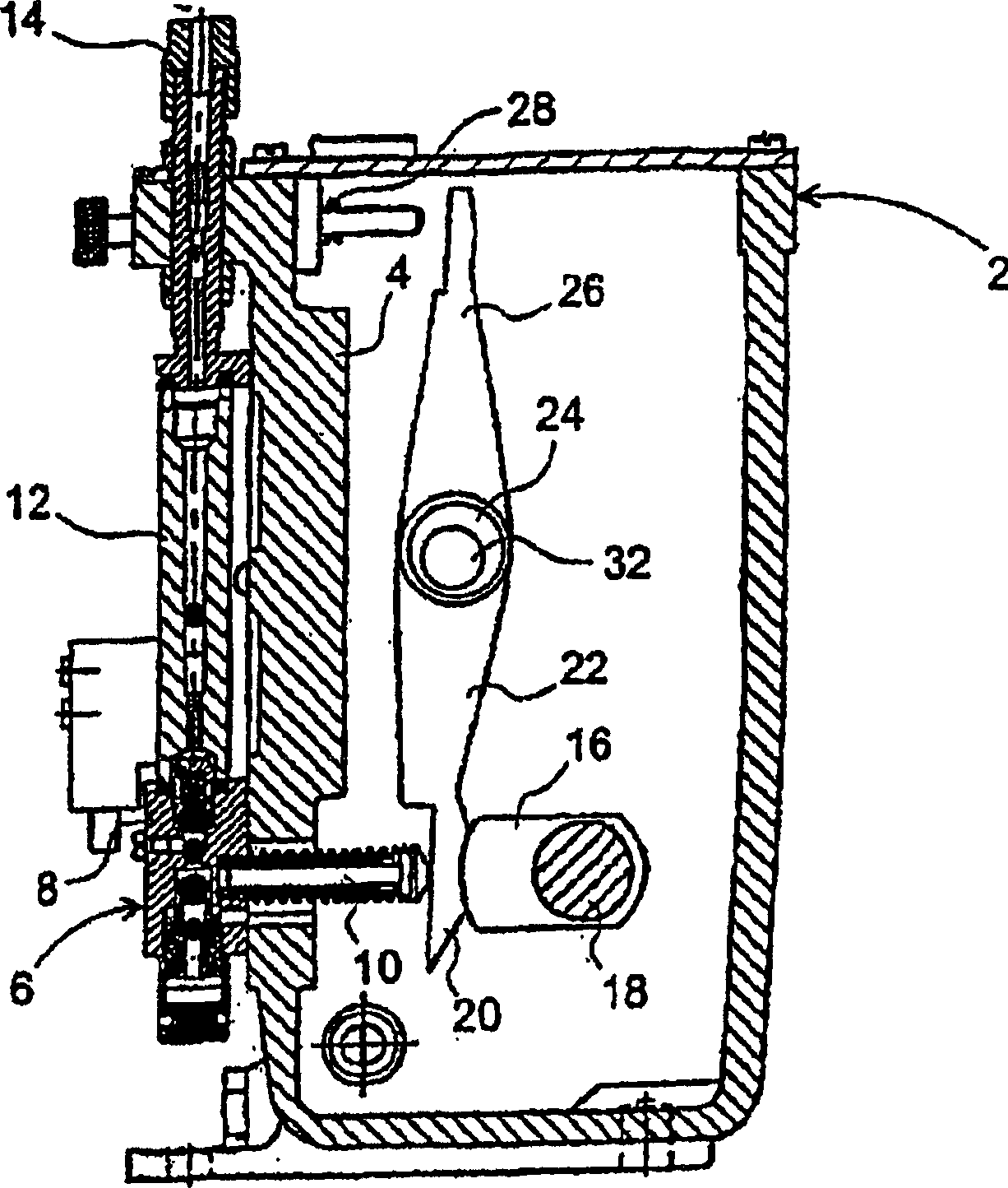
[0051] figure 1 The lubricating device shown in and 2 has a box-shaped equipment housing 2, which supports a row of reciprocating pump units 6 on the front wall 4, figure 1 Only one of them is shown. The unit has a valve housing 8 with a lower lubricating oil inlet, a middle part and an upper reciprocating pump outlet thus formed. The middle part is intended to accommodate a piston 10 which protrudes into the device housing 2 . The outlet is connected via a flow indicator 12 to an upper connector 14, from which connection pipes emanate from the entire row of these connectors to the associated lubrication points on, for example, 6 to 24 cylinders of the engine.

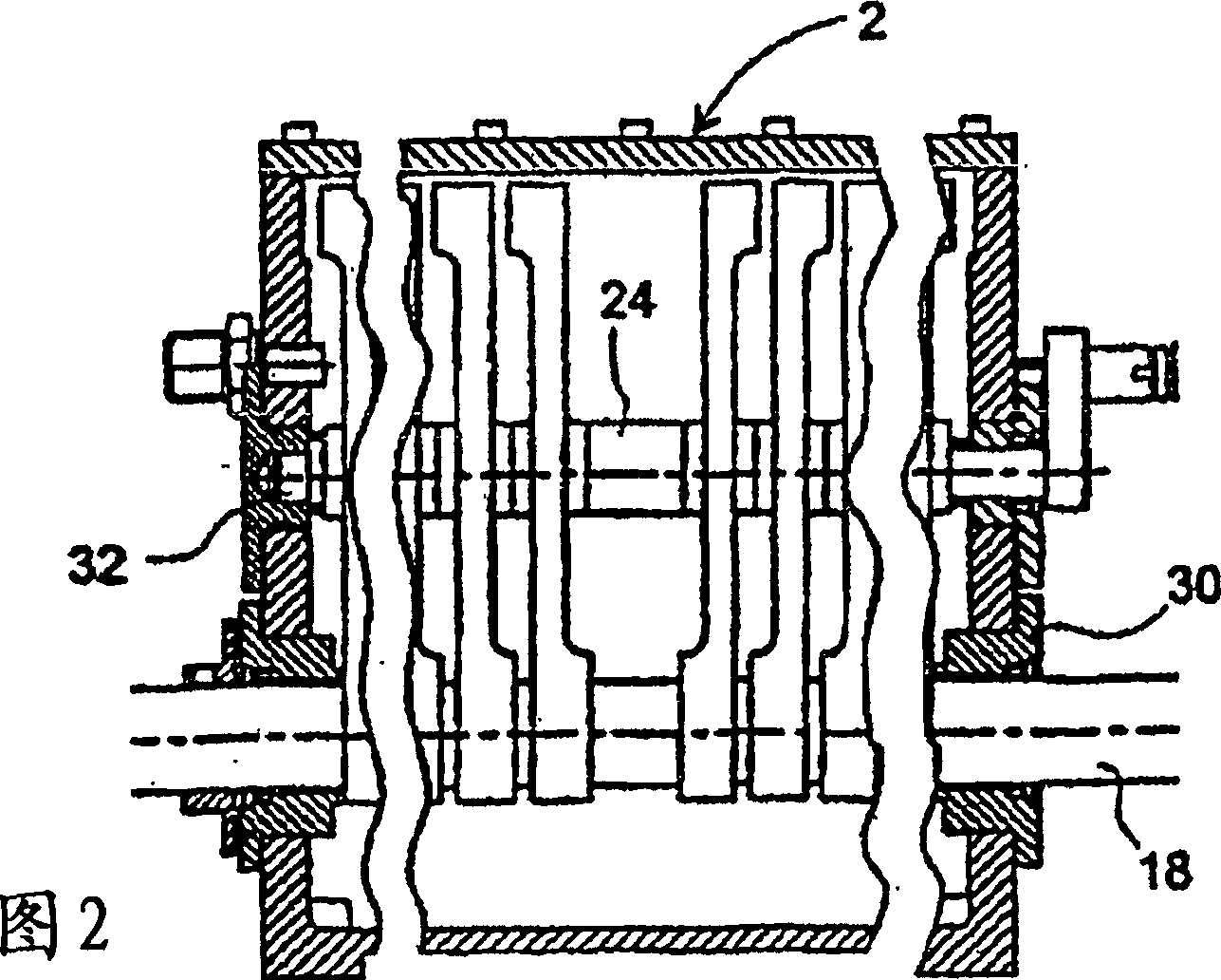
[0052] The piston 10 is driven to press in via a drive cam 16 on a through control shaft 18 . The control shaft 18 rotates synchronously with the crankshaft of the engine and is seated within a bearing housing 30 . The pistons are not driven directly but via thrust pads 20 on the respective rocker arms 22 . The ro...


PUM


Abstract

There is described a centralised lubrication system and a method for lubricating the cylinder faces in large diesel engines, in particular marine engines. The system includes at least one lubricating apparatus (2) having a rotating control shaft (18) for preferably running synchronously with the main shaft (44) of the diesel engine. In order to make a system that does not have a mechanical drive between the lubricating apparatus (2) and the main shaft (44), the system is constructed with an AC motor (36) driving the control shaft (18). Reference means (72, 78) are provided in association with the main shaft (44), indicating the angular position of the main shaft, and sensor means (74, 76, 80) detecting the position of the reference means. Furthermore, the system includes a control unit (40) receiving signals from the sensor means and which includes means for detecting angular position as well as angular speed of the reference means and thereby of the main shaft (44). The control unit (40) is connected with and controls the AC motor (36) for regulating the rotation of the control shaft (18) and thereby actuation of reciprocating pumps providing the cylinder lubrication.

Description

technical field [0001] The present invention relates to a centralized lubrication system for lubricating cylinder faces in large diesel engines, especially marine engines, comprising at least one lubrication unit with a number of reciprocating pumps driven by cams on a rotating control shaft which The shaft is preferably driven synchronously with the main shaft of the diesel engine. [0002] In addition, the invention relates to a method for lubricating cylinder faces in a large diesel engine, especially a marine engine, comprising at least one lubricating device with a number of reciprocating pumps driven by a cam on a rotating control shaft , the rotating control shaft is preferably driven synchronously with the main shaft of the diesel engine. Background technique [0003] Lubricating devices are traditionally designed as pump units mounted in close association with their respective cylinders and connected to a lubricating oil supply tank and to oil injection nozzles at ...

Claims


Application Information

Patent Timeline
Patent Type & Authority Applications(China)
IPC IPC(8): F01M1/02F01M3/04F16N7/38F01M1/08F01M1/14F02D41/34
CPCF01M1/14F02D41/0097F02D41/009F01M2001/083F01M1/02F01M3/04F16N7/38
Inventor I·H·内尔森
Owner HANS JENSEN LUBRICATORS
Why Eureka
Try Eureka