Seismic vibratory acquisition method and apparatus

a technology of seismic vibration and acquisition method, which is applied in the field of seismic vibration acquisition method and apparatus, can solve the problems of inability to distinguish individual reflections from recorded signals, large amount of energy is injected into the earth in a very short period of time, and use of impulsive energy sources can pose certain safety and environmental concerns, so as to improve the utilization of a single vibratory source

Inactive Publication Date: 2006-01-26
WESTERNGECO LLC
View PDF7 Cites 57 Cited by
  • Summary
  • Abstract
  • Description
  • Claims
  • Application Information

AI Technical Summary

Benefits of technology

[0021] The method improves the utilization of a single vibratory source by starting the low frequency sweep within the sweep time of the high frequency sweep. In difference to the existing methods, the present invention uses a shorter low frequency sweep which starts well within the time window of the high frequency sweep. The starting point of the signal can be defined as the point at which the signal begins to contribute noticeable to the load on the drive mechanism of the vibrator. Hence, there exists a starting period during which only the high frequency sweep provides a significant load. The first and second time intervals may end at substantially the same time.

Problems solved by technology

With an impulsive energy source, a large amount of energy is injected into the earth in a very short period of time.
On the other hand, use of an impulsive energy source can pose certain safety and environmental concerns.
Since these composite signals are typically many times longer than the interval between reflections, it is not possible to distinguish individual reflections from the recorded signal.
However, there are other constraints on low frequency output.
Marine vibrators are therefore subject to operational constraints analogous to those of land vibrators.
Another problem with conventional Vibroseis prospecting results from the fact that vibrators generate harmonic distortion as a result of nonlinear effects in the vibrator hydraulics and the ground's nonlinear reaction to the force exerted by the vibrator baseplate, with the second and third harmonics accounting for most of the distortion.
These harmonics are present in the recorded data and lead to trains of correlated noise, known as harmonic ghosts, in the correlated data.
These harmonic ghosts are particularly troublesome in the case of downsweeps where they occur after the main correlation peak (i.e., positive lag times) and, therefore, can interfere with later, hence weaker, reflections.
Nevertheless, harmonic ghosts can cause difficulties in processing and interpreting data from upsweeps as well as from downsweeps.
If the correlation reference sequence includes the additional sweep segment, it complicates the processing in that the additional sweep segment has to be input at negative time giving a nonstandard correlation operator.
While the prior art system has several advantages, it also suffers from a number of drawbacks.
Firstly, starting both high and low frequency sweeps at the same time limits the force that can be generated at the bottom of the high frequency band.
At this point in the sweep, the high-frequency sweep is limited by the hydraulic and stroke limitations of the vibrator, but to add a low-frequency sweep at the same time reduces the available resource for the high-frequency sweep.
Secondly, hydraulic vibrators inevitably generate energy not just at the desired frequency, but also at harmonics of that frequency.
As a result, correlating the reflected seismic signals with the summed sweeps, i.e. with the drive to the vibrator, may lead to artifacts appearing in the seismogram at the overlap frequencies and reduces the opportunity for spectral balancing.

Method used


Image

  • Seismic vibratory acquisition method and apparatus
  • Seismic vibratory acquisition method and apparatus
  • Seismic vibratory acquisition method and apparatus

Examples


Embodiment Construction

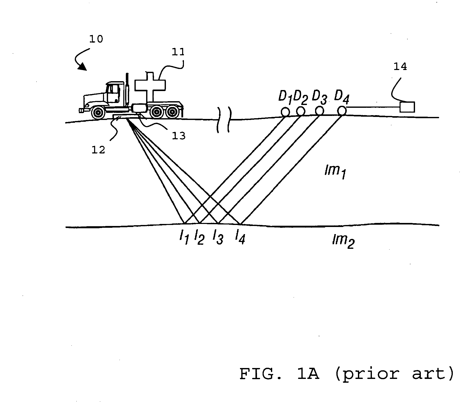
[0040] The system of FIG. 1A illustrates in a simplified manner a Vibroseis acquisition using a vibrator 11 with a baseplate 12 and a signal measuring apparatus 13, for example accelerometers, whose signals are combined to measure the actual groundforce signal applied to the earth, all located on a truck 10.

[0041] The signal that is generated into the earth by vibrator 11 is reflected off the interface between subsurface impedances Im1 and Im2 at points I1, I2, I3, and I4. This reflected signal is detected by geophones D1, D2, D3, and D4, respectively. The signals generated by vibrator 11 on truck 10 are transmitted to a data storage 14 for combination with raw seismic data received from geophones D1, D2, D3, and D4 and further processing.

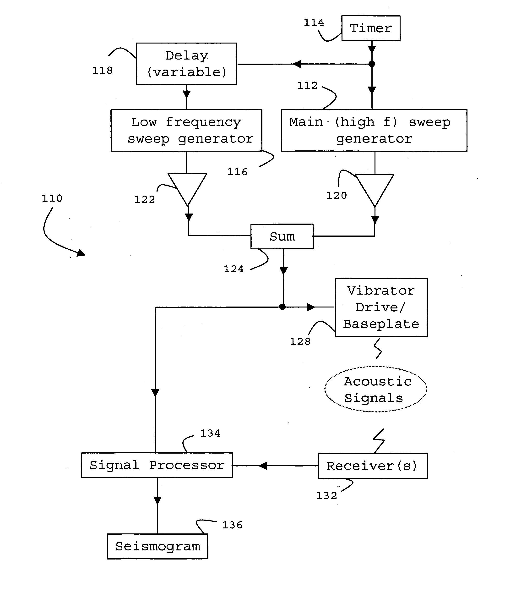
[0042] In operation a control signal, referred to also as pilot sweep, causes the vibrator hydraulics 11 to exert a variable pressure on the baseplate 12.

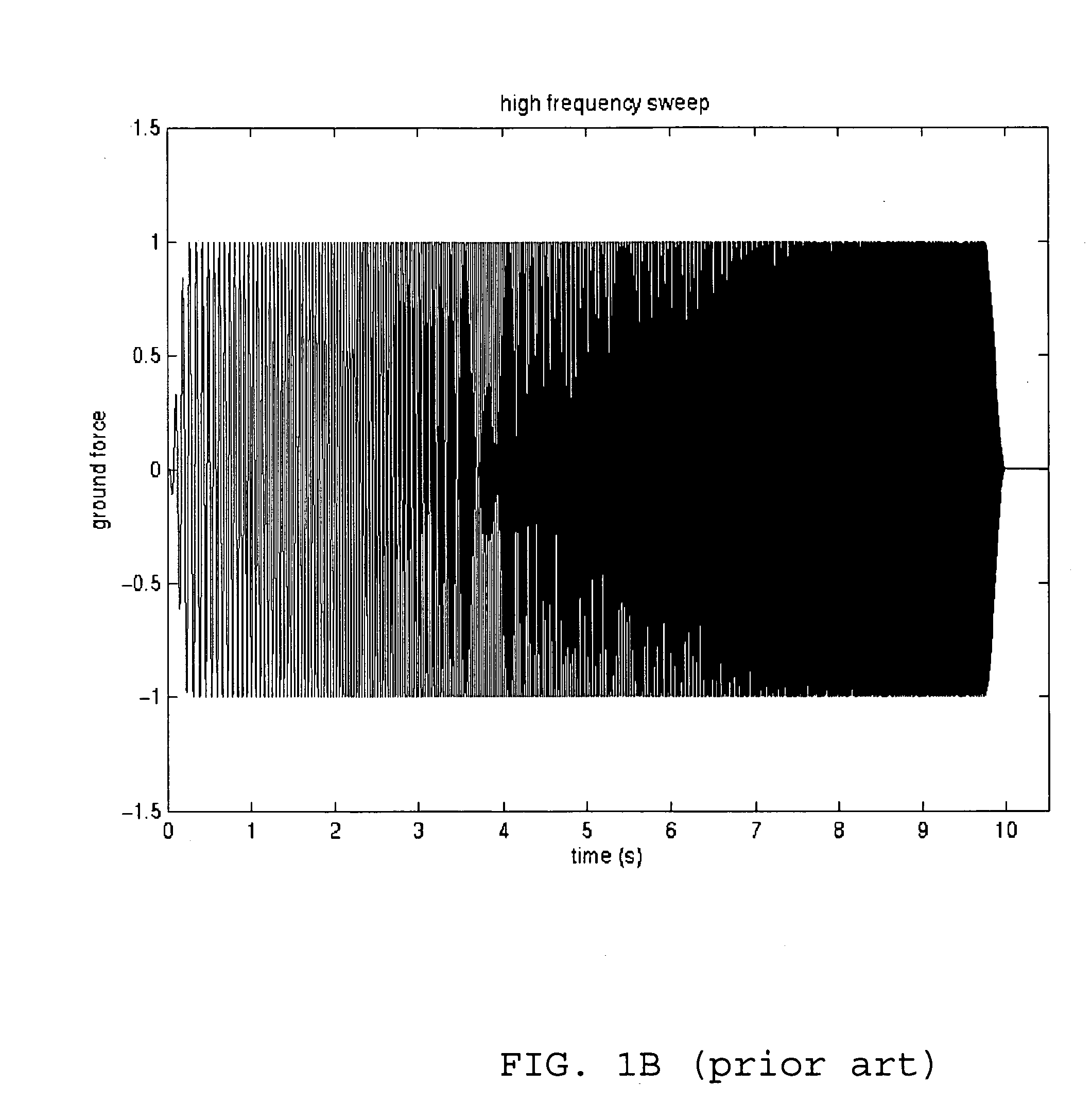
[0043] As can be seen in FIG. 1B, a typical prior art high frequency sweep goes from 10 Hz ...


PUM


Abstract

A method and related apparatus are described for generating acoustic signals for use in a vibratory seismic survey, including the step of combining into a drive signal a high frequency sweep signal, which sweeps upwardly through a high frequency band during a first time interval, and a low frequency sweep signal which is of lower amplitude than the high frequency sweep signal and which sweeps upwardly through a low frequency band during a second time interval, wherein the second time interval starts during the first time interval but after the beginning thereof; and applying the drive signal to a mechanical drive system for a vibratable element. The method improves the utilization of a single vibratory source.

Description

[0001] This invention relates to seismic surveying, and is more particularly concerned with the seismic surveying of earth formations using an acoustic source in the form of a vibrator which imparts a variable frequency signal into the earth formations, either directly in the case of surveying on land, or via water in the case of marine seismic surveying. BACKGROUND OF THE INVENTION [0002] In the oil and gas industry, geophysical prospecting techniques are commonly used to aid in the search for and evaluation of subterranean hydrocarbon deposits. Generally, a seismic energy source is used to generate a seismic signal that propagates into the earth and is at least partially reflected by subsurface seismic reflectors (i.e., interfaces between underground formations having different acoustic impedances). The reflections are recorded by seismic detectors located at or near the surface of the earth, in a body of water, or at known depths in boreholes, and the resulting seismic data may b...

Claims


Application Information

Patent Timeline
Patent Type & Authority Applications(United States)
IPC IPC(8): G01V1/00
CPCG01V1/005G01V1/02
Inventor JEFFRYES, BENJAMIN P.MARTIN, JAMES EDWARD
Owner WESTERNGECO LLC
Why Eureka
Try Eureka