Channel structure of vacuum cleaner

A technology of vacuum cleaner and channel structure, applied in the direction of suction filter, etc., can solve the problems of increasing the volume of the dust collecting device and reducing the working efficiency, and achieve the effect of reducing the volume, improving the dust collecting efficiency and increasing the cleaning efficiency.

Inactive Publication Date: 2006-12-13
LG ELECTRONICS (TIANJIN) APPLIANCES CO LTD
View PDF0 Cites 77 Cited by
  • Summary
  • Abstract
  • Description
  • Claims
  • Application Information

AI Technical Summary

Problems solved by technology

Moreover, when the multi-cyclone dust collection method is used, the volume of the dust collection device will increase. Therefore, on the premise of keeping the volume of the vacuum cleaner unchanged, in order to avoid the reduction of the working efficiency of the vacuum cleaner, it is necessary to properly design the internal structure of the vacuum cleaner.

Method used


Image

  • Channel structure of vacuum cleaner
  • Channel structure of vacuum cleaner
  • Channel structure of vacuum cleaner

Examples


Embodiment Construction

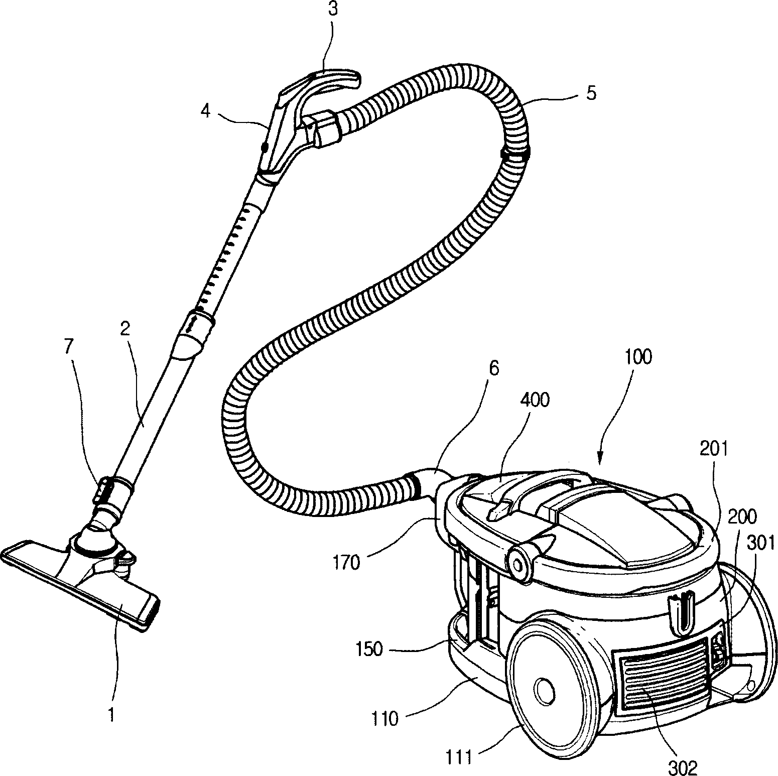
[0019] figure 1 The three-dimensional structure diagram of the vacuum cleaner provided by the present invention. Such as figure 1 As shown, the vacuum cleaner provided by the present invention includes a body 100 and a suction pipeline connected to the suction side of the body 100 . The inside of the main body 100 is at least installed with a suction fan and a dust collection device, so that the external air can be sucked in and the foreign matter can be filtered out and then discharged to the outside. The suction pipeline is a pipeline that utilizes the suction inside the vacuum cleaner body 100 to suck air and foreign matter together. Specifically, the suction pipeline includes: a suction nozzle 1 that sucks air mixed with foreign matter from the outside; an extension tube 2 that extends from the suction nozzle 1 and can be stretched according to the use state; 2. The operating handle 3 at the end; the operating part 4 that is arranged on the front portion of the operatin...


PUM


Abstract

The invention discloses a channel structure of vacuum cleaner, which comprises the following parts: dust collecting device of filtered air, motor rack to lead air of dust collecting device under motor exposing condition, bulk vent on the back of vacuum cleaner to discharge the air through motor. The invention improves the utility rate of vacuum cleaner, which reduces channel resistance.

Description

technical field [0001] The invention relates to a dust collecting device of a vacuum cleaner, in particular to a channel structure of a vacuum cleaner which can be well adapted to adopting multiple cyclone dust collecting devices. Background technique [0002] A vacuum cleaner is a device that collects and collects foreign matter in the air sucked by the vacuum pressure inside the machine, thereby cleaning the external environment. The interior of the vacuum cleaner is equipped with a dust collection device that can separate foreign objects in the inhaled air, and the interior of the dust collection device is equipped with a filter device. The filter device includes: a filter device made of porous material that collects foreign matter when the air flows through it, and a cyclone filter device that removes foreign matter in the air by using the cyclone air flow formed by the air. The filter device made of the porous material is difficult to clean after filtering the air, and...

Claims


Application Information

Patent Timeline
Patent Type & Authority Applications(China)
IPC IPC(8): A47L9/16
Inventor 郑会吉黄万泰金永浩黄正裴朴民崔在浩
Owner LG ELECTRONICS (TIANJIN) APPLIANCES CO LTD
Why Eureka
Try Eureka