Oil pump driving control device for a hybrid vehicle
A hybrid vehicle, oil pump technology, applied in hybrid vehicles, power units, control devices, etc., to achieve the effects of light weight, reduction in number, and simplification of hydraulic circuits
- Summary
- Abstract
- Description
- Claims
- Application Information
AI Technical Summary
Problems solved by technology
Method used
Image

Examples
Embodiment 2
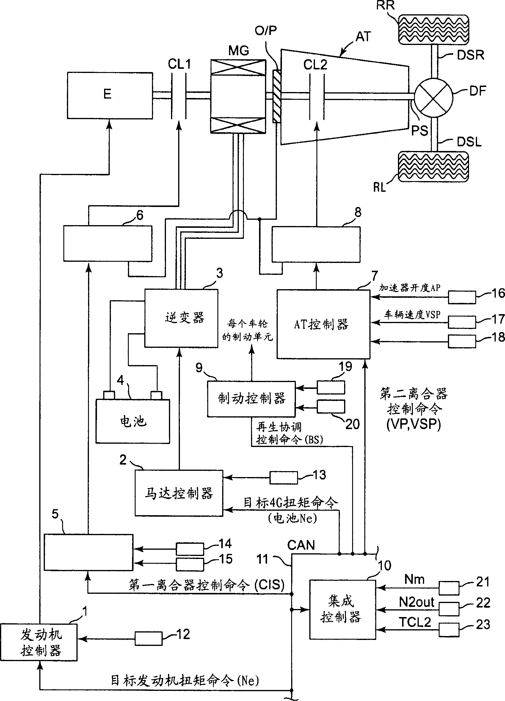
[0062] Example 2. Embodiment 2 is an example in which the rotation of the motor-generator is maintained at a high level when starting off by slipping the second clutch through the motor-generator. Because the system is formed with figure 1 Same, so drawing and description are omitted. Figure 4 is a flowchart showing the flow of an example oil pump drive control process executed by the integrated controller of Embodiment 2. In addition, a description of the processing of each of steps S201 to S209 is omitted because they are related to figure 2 The processing of each step from step S101 to step S109 in the flowchart shown in is the same.
[0063] In step S212, which is a continuation of the accelerator "on" determination of step S204, it is determined whether the accelerator opening is greater than 2 / 8 (threshold value considering that the accelerator pedal is depressed greatly), and, if "yes", proceed Go to step S214, and if "No", go to step S213. In step S213 which is ...
Embodiment 3
[0076] Example 3. Embodiment 3 is an example of the operation of the mechanical oil pump by detecting the hydraulic pressure generated by the pump when the hydraulic pressure is reduced by deceleration or stop. The system structure is the same as that of Embodiment 1, so drawing and description are omitted.
[0077] Figure 6 is a flowchart showing the flow of an example oil pump drive control process executed by the integrated controller of Embodiment 3. The processing of each step from step S301 to step S311 is the same as the processing of each step from step S101 to step S111 , and thus description thereof will be omitted. In step S312, continue the determination of selection R and D in step S302, determine whether the accelerator and foot are disengaged, if "Yes", then proceed to step S303, and if "No", then proceed to step S310.
[0078] In step S313, continuing the determination of the brake being "on" in step S303, it is determined whether the speed of the vehicle i...
Embodiment 4
[0090] Example 4. Embodiment 4 is an example in which the stop of the mechanical oil pump operation is controlled by a timer using a detection signal of the running condition of the vehicle as a trigger. The detection signal is provided by a detection component (detector) which detects the driving condition of the vehicle. Because the system structure is the same as that of Embodiment 1 figure 1 Same, so, omit drawing and description.
[0091] Figure 8 is a flowchart showing the flow of an example oil pump drive control process executed by the integrated controller of Embodiment 4. In addition, the description of the processing of each step from step S410 to step S405 and step S407 to step S411 is omitted because the processing is similar to figure 2 The processing of steps S101 to S105 and steps S107 to S111 shown in . In step S412 continuing based on the brake ON determination of step S403, it is determined whether the vehicle is stopped, and if yes, proceed to step S...
PUM
 Abstract
Description
Claims
Application Information
 - Generate Ideas
- Intellectual Property
- Life Sciences
- Materials
- Tech Scout
- Unparalleled Data Quality
- Higher Quality Content
- 60% Fewer Hallucinations
Browse by: Latest US Patents, China's latest patents, Technical Efficacy Thesaurus, Application Domain, Technology Topic, Popular Technical Reports.
© 2025 PatSnap. All rights reserved.Legal|Privacy policy|Modern Slavery Act Transparency Statement|Sitemap|About US| Contact US: help@patsnap.com