Air feeding and control device for the pneumatic transporting of the weft in air-jet weaving machines

A technology of pneumatic conveying and air-jet looms, which can be used in looms, textiles, papermaking, textiles, etc., and can solve problems such as energy loss

Inactive Publication Date: 2006-12-13
SMIT S P A UNIPERSONALE
View PDF0 Cites 14 Cited by
  • Summary
  • Abstract
  • Description
  • Claims
  • Application Information

AI Technical Summary

Problems solved by technology

During this period the weft yarn is held causing energy loss

Method used


Image

  • Air feeding and control device for the pneumatic transporting of the weft in air-jet weaving machines
  • Air feeding and control device for the pneumatic transporting of the weft in air-jet weaving machines
  • Air feeding and control device for the pneumatic transporting of the weft in air-jet weaving machines

Examples


Embodiment Construction

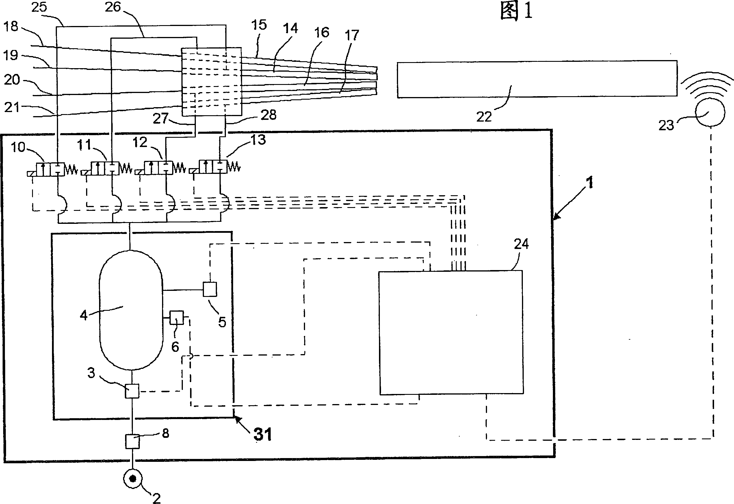
[0015] Referring now in particular to Figure 1, which relates to a particularly illustrative and preferred but non-limiting embodiment of the invention, an air feed system for pneumatically conveying weft yarns is indicated generally at 1, and which system mainly includes a control system 24. Air accumulation and feeding system 31 which requires a source of compressed air 2 stabilized by a pressure regulator 8, and a series of Electrovalves 10, 11, 12, 13 (since the system described as an example enables the insertion of four weft threads, there are four electrovalves in the pneumatic conveying device illustrated in Figure 1).

[0016] The air accumulation and feeding system 31 consists of a flow regulator 3 , a container 4 , an electrovalve 5 and a pressure sensor 6 in sequence.

[0017] The operating cycle of the system can be divided into two basic phases: the first phase, during which the electric valves 10, 11, 12, 13 are closed and thus no air flows to the nozzles 14, 15...


PUM


Abstract

Air feeding and control device for the pneumatic transporting of the weft (18-21) in air-jet weaving machines, comprising a control system (24), connected to air feeding means, which comprise a compressed air source (2) and a series of nozzles (14-17), driven by respective electrovalves (10-13) and which can be used for inserting the weft; the air feeding means also comprise at least one air feeding and accumulation system (31), suitable for allowing a pre-established quantity of air to be accumulated when the air is not flowing to the nozzles (14-17) and suitable for regulating the air flow-rate when it is flowing to the nozzles (14-17).

Description

technical field [0001] The present invention relates to an air feed and control device for pneumatically conveying weft yarns in an air-jet weaving machine, such as a loom, and more particularly, to a device suitable for regulating the flow of air to the nozzles during weft insertion. (flow-rate) device. Background technique [0002] Methods are known for feeding a series of nozzles in air-jet looms, wherein said nozzles deliver compressed air energy to the weft threads; Stable over time, it is necessary to control the reverse action on the parameters that affect it, such as pressure, timing, etc. [0003] This known method uses a pressure control system feeding a series of electrovalves of the on / off type connected by conduits to weft insertion nozzles. [0004] In the operation of a system of the type described above, a certain time is necessary so that, once the electrovalve is opened, the air can reach the flow inside the duct and the nozzle to allow effective accelera...

Claims


Application Information

Patent Timeline
Patent Type & Authority Applications(China)
IPC IPC(8): D03D47/30
CPCD03D47/3053D03D47/3033
Inventor R·卡皮塔尼奥M·诺韦拉
Owner SMIT S P A UNIPERSONALE
Why Eureka
Try Eureka