Method for production of sandwich panels with zigzag corrugated core

A zigzag and plywood technology is applied in the field of producing plywood with a twisted and wrinkled core, which can solve the problems of reduced strength of the plywood, affecting the strength of the core-skin connection, unfavorable deformation conditions, etc., and achieves the effect of improving product quality.

A zigzag and plywood technology is applied in the field of producing plywood with a twisted and wrinkled core, which can solve the problems of reduced strength of the plywood, affecting the strength of the core-skin connection, unfavorable deformation conditions, etc., and achieves the effect of improving product quality.

CN1878625AInactive Publication Date: 2006-12-13KAZAN AVIATION IND SCI RES INST JOINT CO +1

Image

  • Method for production of sandwich panels with zigzag corrugated core
  • Method for production of sandwich panels with zigzag corrugated core
  • Method for production of sandwich panels with zigzag corrugated core

Examples


Embodiment Construction

[0016] Our method can be implemented in the following way:

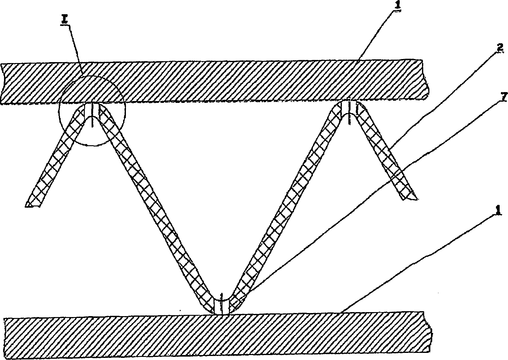
[0017] 1) manufacture the outer skin and inner skin 1 of the splint;

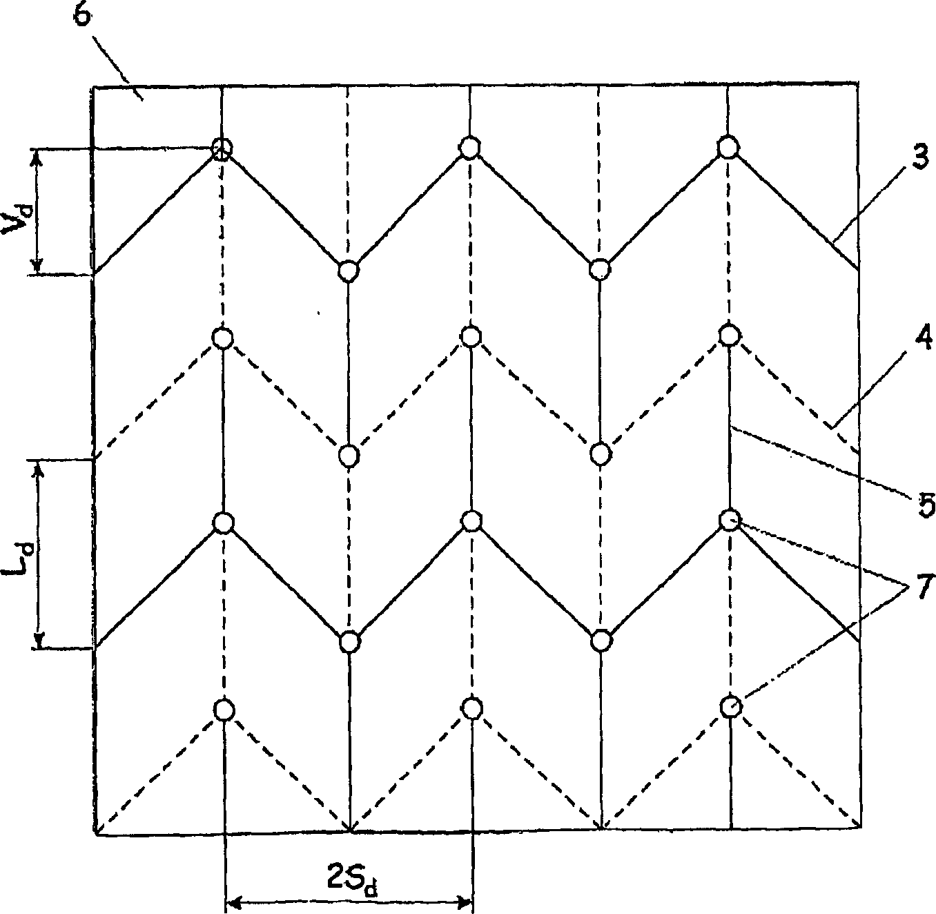
[0018] 2) Draw the bending lines 3, 4, 5 on the chip blank 6 of the core 2; the parameters and relative positions of the bending lines 3, 4, 5 are related to the design parameters of the core 2:

[0019] L d =f(H,L); V d =f(V, L d );S d =f(V,S,H,L),

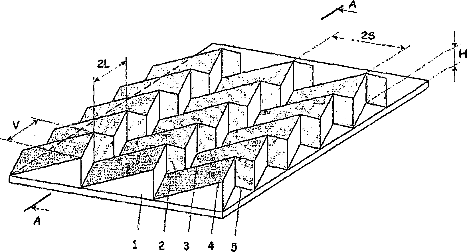
[0020] where H is the height of the zigzag folds, V is the amplitude of the zigzag lines, 2S is the step between the zigzag lines, 2L is the step between the zigzag lines, with the dimensions unfolded: 2S d is the step distance between the zigzag lines, L d is the distance between the meander lines, V d is the magnitude of the meander line;

[0021] 3) Punch holes 7 in the blank at the intersection of the zigzag line 5 and the meander lines 3, 4; the diameter of these holes 7 is d h ≥R b , where R b is the bend radius of the chip blank at the intersection of the jagged line 5 and the meand...


PUM


Abstract

The invention can be defined in its most general form as a method for production of sandwich panels with zigzag corrugated core (2) from sheet material used in aircraft construction, shipbuilding, and other branches of industry.With the aim to improve the quality and ease of sheet blank folding into the 3-D relief structure in the sheet blank at locations of crimp zigzag lines (4) protrusions and recesses the holes are punched with the diameter not less than the sheet blank bending radius.

Description

technical field [0001] Our invention can be defined in the broadest sense as a method of producing plywood with a meandering corrugated core made of sheet material, which is used in aircraft construction, shipbuilding and other industries. Background technique [0002] A method for producing plywood with a meandering corrugated core comprising forming a core and a skin separately, wherein the core is produced by bending a sheet blank along scribed protrusion and recess meander lines, such The method was taken as a prototype (Certificate of Invention No. 1,785,154USSR, International Classification No. B23K20 / 00, Method of Manufacturing Curvilinear Plywood with Zigzag Corrugated Core, Proclamation of Purpose 30.07.93, Article 28). [0003] The main disadvantage of the method described here is the increased material due to the spreading effect in the nodal region. This effect occurs when the corrugated core is formed in its knuckles, which is where at least four ridges of the ...

Claims


Application Information

Patent Timeline
13 Dec 2006
Publication
CN1878625A
IPC
B21D47/00; B32B3/28; E04C2/34; B21D47/04
CPC
Y10T428/1234; Y10T29/49995; B21D47/00; Y10T29/49623; Y10T29/49629; Y10T29/49627; B32B3/28; B32B2605/18
Inventors
N·I·阿基舍夫; I·M·扎基罗夫