Variable displacement swash plate type compressor

A variable and swash plate technology, applied in the direction of liquid variable displacement machinery, mechanical equipment, machine/engine, etc., can solve problems such as reduction, compression reaction force increase, and deterioration of durability

Inactive Publication Date: 2006-12-13
TOYOTA IND CORP
View PDF2 Cites 14 Cited by
  • Summary
  • Abstract
  • Description
  • Claims
  • Application Information

AI Technical Summary

Problems solved by technology

Therefore, in the swash plate type compressor, the compression reaction force acting on the piston 94 becomes larger, further exacerbating the above-mentioned problems (the durability of the second swash plate 95 and the second shoe 93B decreases).

Method used


Image

  • Variable displacement swash plate type compressor
  • Variable displacement swash plate type compressor
  • Variable displacement swash plate type compressor

Examples


Embodiment Construction

[0037] Next, first to fourth embodiments in which the present invention is embodied as a capacity-variable swash plate compressor constituting a refrigeration circuit of a vehicle air conditioner will be described.

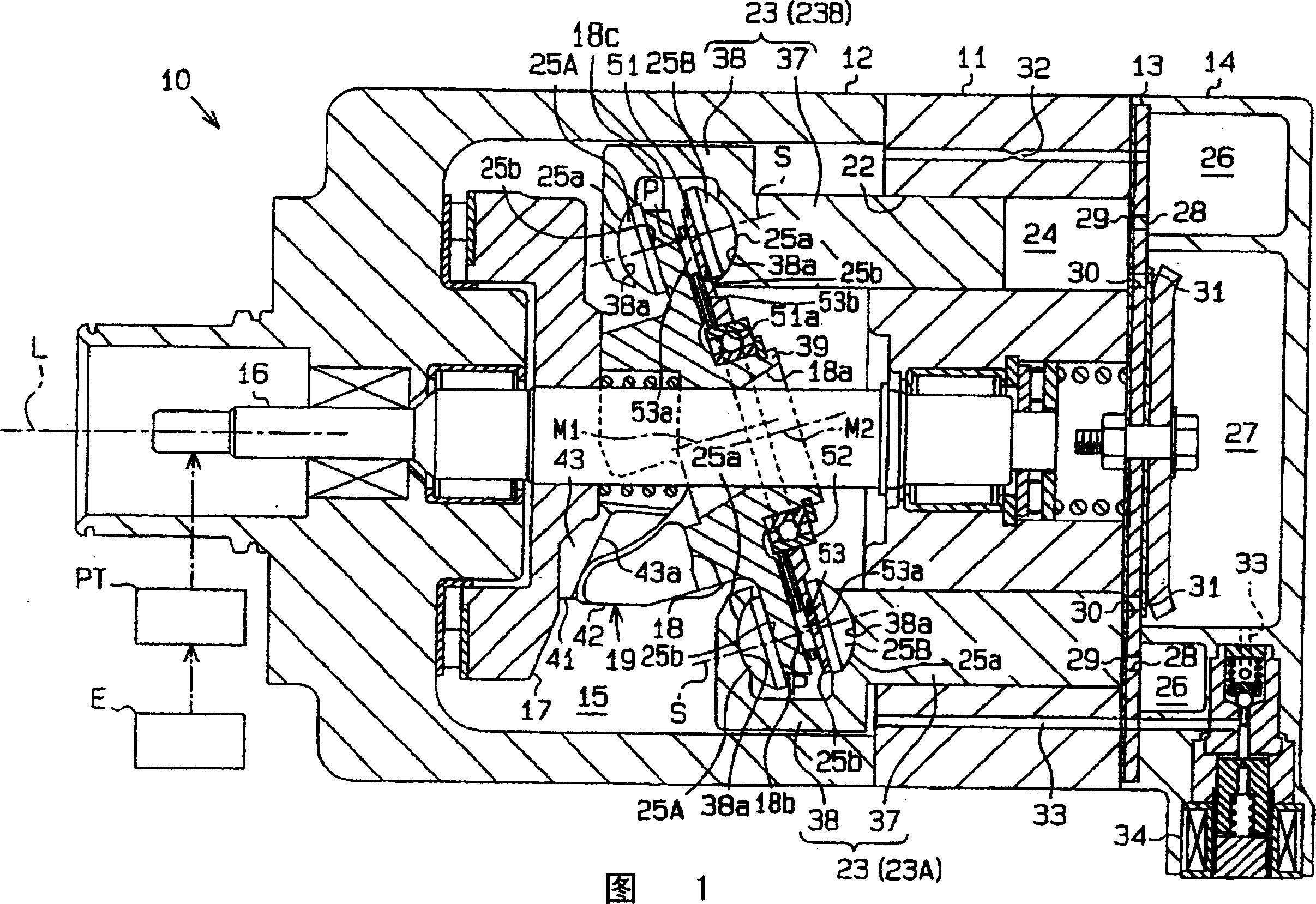
[0038] For the first embodiment, referring to Fig. 1 and figure 2 Be explained. FIG. 1 shows a longitudinal sectional view of a variable capacity swash plate compressor (hereinafter referred to as compressor 10). In FIG. 1 , the left side is the front of the compressor 10 , and the right side is the rear side of the compressor.

[0039] As shown in FIG. 1 , the casing of the compressor 10 is equipped with: a cylinder block 11 , a front casing 12 fixed to the front end of the cylinder block 11 , and a rear end of the cylinder block 11 via a valve and port forming body 13 . ground fixed rear case 14.

[0040] In the casing of the compressor 10 , a crank chamber 15 is defined between the cylinder block 11 and the front casing 12 . A drive shaft 16 is rotatably d...


PUM


Abstract

A variable displacement swash plate type compressor, wherein a first swash plate (18) is connected to a drive shaft (16) so as to be rotated integrally with each other and double-head pistons (23) are anchored to the first swash plate (18) through shoes (25A) and (25B). The pistons (23) are reciprocatingly moved in the linear direction by the rotation of the first swash plate (18) according to the rotation of the drive shaft (16) to compress refrigerant gas. An annular second swash plate (51) is supported on the first swash plate (18) rotatably relative to each other through a ball bearing (52). The second swash plate (51) is disposed between the first swash plate (18) and the shoes (25B) on a compressive load receiving side slidably on the first swash plate (18) and the shoes (25B). Sloped faces (chamfered parts) are formed at the projected corner parts (18b) and (18c) of the first swash plate (18). Accordingly, the durability of the swash plates and the shoes can be increased.

Description

technical field [0001] The present invention relates to, for example, a swash plate compressor that constitutes a refrigeration circuit and compresses refrigerant gas. Background technique [0002] Such as Figure 9 As shown, in this kind of swash plate compressor, a swash plate 92 is connected to the drive shaft 91 so as to be integrally rotatable. On the outer peripheral portion of the swash plate 92, a single-headed piston 94 is attached via a pair of hemispherical shoes 93A, 93B, respectively. Therefore, when the swash plate 92 is rotated by the rotation of the drive shaft 91, the swash plate 92 slides with respect to the shoes 93A, 93B, and the piston 94 performs linear reciprocating motion to compress the refrigerant gas. [0003] Sliding shoes 93A and 93B rotate relative to the swash plate 92 around their own axis S (a line passing through the center of spherical curvature P and perpendicular to the sliding surface of the swash plate 92 ). The rotational movement of...

Claims


Application Information

Patent Timeline
Patent Type & Authority Applications(China)
IPC IPC(8): F04B27/12
Inventor 栗田创今井崇行村濑正和深沼哲彦太田雅树榎岛史修
Owner TOYOTA IND CORP
Why Eureka
Try Eureka