Visual inspection lighting device based on reflective light and transmission light

A visual inspection and lighting device technology, applied in the direction of measuring devices, optics, nonlinear optics, etc., can solve the problems that cannot be obtained, cannot be irradiated with converging light, and cannot distinguish the vertical position of defects, so as to achieve high degree of freedom and reduce defects Missing rate, effect of enhancing defect visibility

Inactive Publication Date: 2006-12-20
MORITEX CORP
View PDF1 Cites 7 Cited by
  • Summary
  • Abstract
  • Description
  • Claims
  • Application Information

AI Technical Summary

Problems solved by technology

[0006] 1) Illuminators using milky white acrylic diffusers in tri-primary fluorescent lamps can only be used for inspections based on transmitted light
[0007] 2) Due to the use of fluorescent lamps for lighting, the color cannot be changed to colors of different wavelengths suitable for various defect types when performing inspections
On the other hand, the light of fluorescent lamps is scattered light, and convergent light other than scattered light, which is effective for defect observation, cannot be irradiated.
Furthermore, since the light diverges, the illuminance decreases in inverse proportion to the square of the distance between the above-mentioned illumination source and the above-mentioned inspection object, and inspection at a sufficient illuminance level cannot be performed.
[0008] 3) In the lighting of fluorescent lamps, the color temperature is 3000 to 5000°K, and the light of 6000°K close to sunlight suitable for inspection cannot be obtained
In this way, when observing defects, the defect visibility and color visibility are low, and the defect omission rate is high
[0010] 5) In the inspection based on transmitted light, the vertical position (concavity and convexity) of the defect cannot be distinguished according to the type of defect of the inspection object
Furthermore, since only scattered light can be used, it is easy to miss tiny defects

Method used


Image

  • Visual inspection lighting device based on reflective light and transmission light
  • Visual inspection lighting device based on reflective light and transmission light
  • Visual inspection lighting device based on reflective light and transmission light

Examples


Embodiment Construction

[0034] Modes for carrying out the invention will be described below with reference to the drawings.

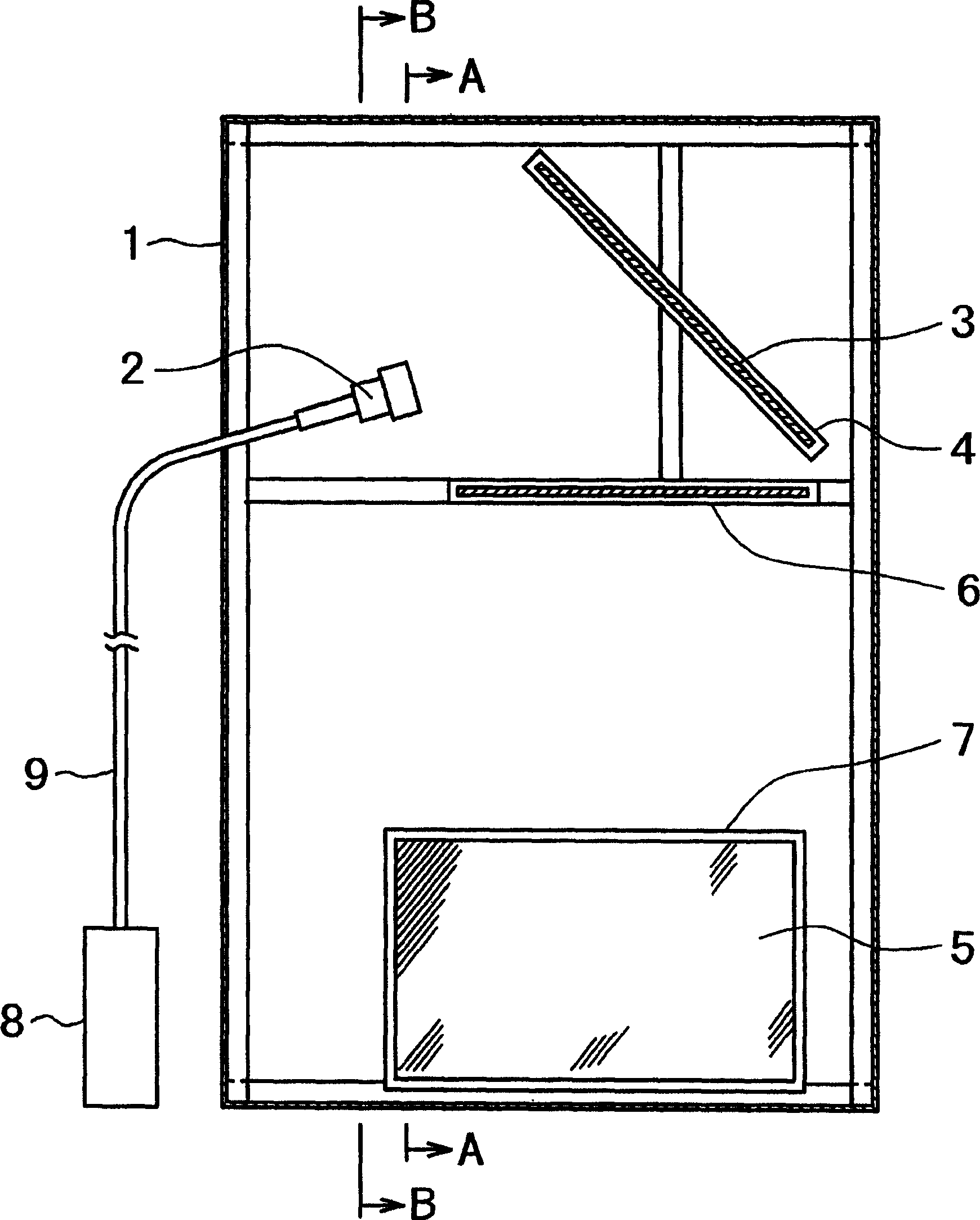
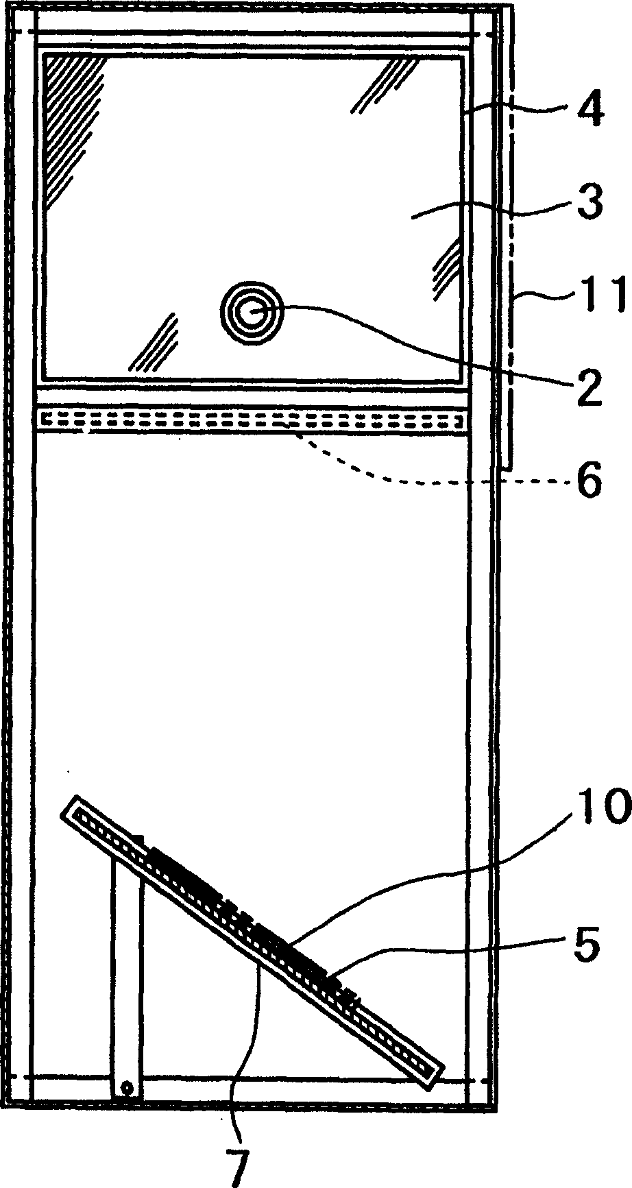
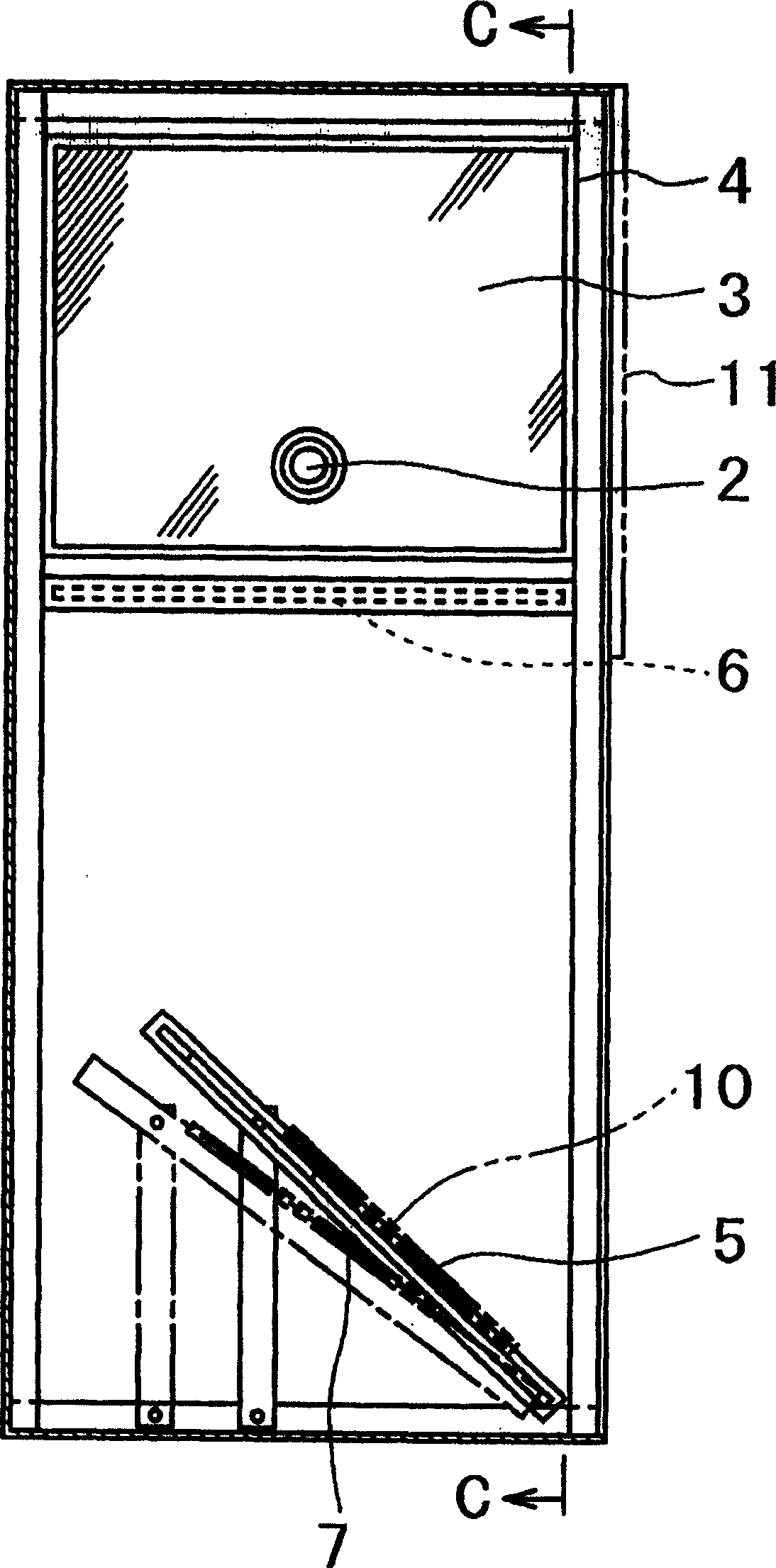
[0035] figure 1 It is a schematic cross-sectional view showing the front side of an embodiment of the lighting device for visual inspection of the present invention. figure 2 is along figure 1 Sectional view of line A-A. image 3 is used to schematically illustrate the mirror adjustment action along the figure 1 Sectional view of the B-B line. Figure 4 is used to schematically illustrate the mirror adjustment action along the image 3 Sectional view of line C-C.

[0036] In these figures, reference numeral 1 denotes a box-shaped casing formed with an open front. On the upper part of the housing 1, a light emitting part 2 for emitting illumination light is installed on the left side of the figure, and an inclined reflector 3 is installed on the right side of the figure so as to face the light emitting part 2. Such as Figure 4 As shown in , the frame portion 4 of the ...


PUM


Abstract

The invention relates to a visual checking lighting device, which is based on reflective light and transmission light. Wherein, it is characterized in that: the upper part of frame (1) is arranged with the light emitter (2) for emitting light and the incline mirror (3) opposite to the emitter; the lower part of frame is arranged with the incline transmission light mirror (5) for checking object; and a Fresnel lens (6) is arranged between the mirror and the transmission light mirror.

Description

technical field [0001] The present invention relates to an illumination device for visual inspection of various inspection objects such as polarizing films and liquid crystal substrates, and more particularly to an illumination device for visual inspection based on both reflected light and transmitted light. Background technique [0002] In conventional inspections for detecting defects in inspection objects such as polarizing films, in most cases, a transilluminator equipped with a milky white acrylic diffuser in a trichromatic fluorescent lamp is used so as to use light emitted from the fluorescent lamp Scattering sheet and through the scattered light of the above inspection object for visual inspection. [0003] On the other hand, Patent Document 1 describes a method of inspecting an optical sheet constituted by laminating polarizing reflective sheets as an inspection object and irradiating light obliquely thereon to inspect defects based on light reflected from the optic...

Claims


Application Information

Patent Timeline
Patent Type & Authority Applications(China)
IPC IPC(8): G02B5/30G02F1/13G01N21/958
CPCG01M11/00G01N21/88G01N21/8803G01N21/958G02F1/335
Inventor 窪田勉松本和幸今村保夫
Owner MORITEX CORP
Why Eureka
Try Eureka