Color display unit

A color display, blue technology, used in identification devices, instruments, optics, etc., can solve problems such as large ultraviolet light absorption, poor efficiency, and component degradation

Inactive Publication Date: 2006-12-20
SEIKO INSTR INC
View PDF1 Cites 33 Cited by
  • Summary
  • Abstract
  • Description
  • Claims
  • Application Information

AI Technical Summary

Problems solved by technology

[0003] However, in the conventional structure of mixing fluorescent materials in the color filter, the excitation light is ultraviolet light, which means the fact that the ultraviolet light in the liquid crystal cell is greatly absorbed, resulting in poor efficiency, and the ultraviolet light affects liquid crystal molecules or liquid crystal alignment , and there is a risk of promoting component degradation

Method used


Image

  • Color display unit
  • Color display unit
  • Color display unit

Examples


Embodiment 1

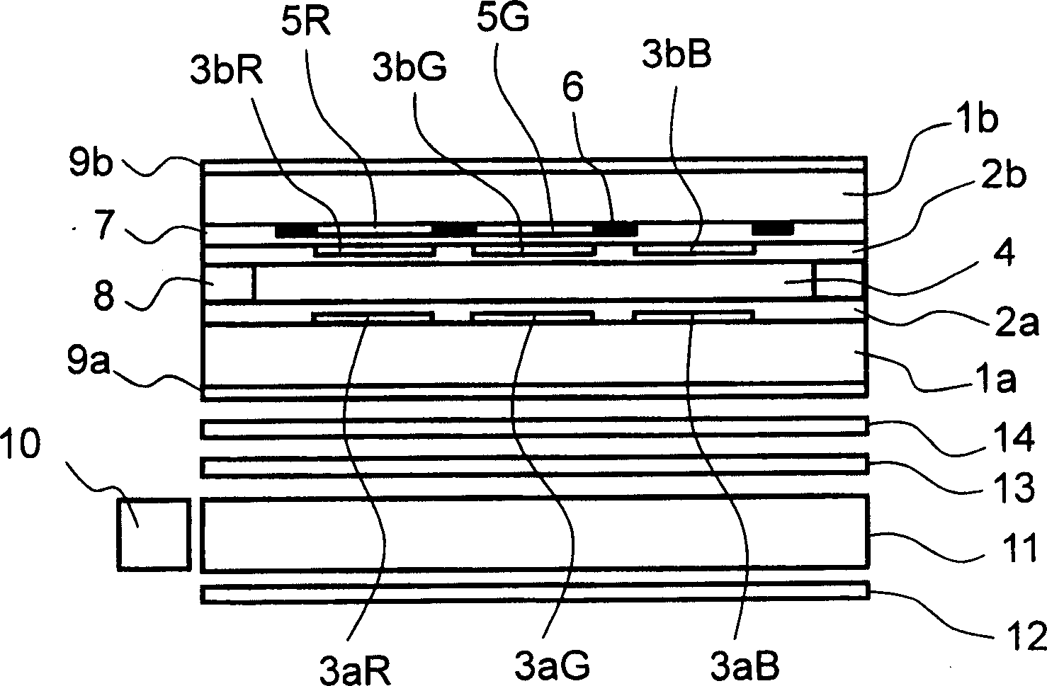
[0031] figure 2 The cross-sectional structure of the display unit of this embodiment is schematically shown. Such as figure 2 As shown, the liquid crystal element is configured to have the liquid crystal layer 4 enclosed in the gap between the glass substrate 1a and the opposing substrate 1b. Transparent electrodes 3aR, 3aG, 3aB and an orientation film 2a on the transparent electrode are formed on the glass substrate 1a. On the other hand, a red fluorescent material layer 5R and a green fluorescent material layer 5G are formed on the opposite substrate. A black matrix 6 is formed in the gap between these fluorescent material layers (except for the blue area). The formation regions of the red fluorescent material layer 5R, the green fluorescent material layer 5G, and the black matrix 6 are flattened using the flattening layer 7. The transparent electrodes 3bR, 3bG, and 3bB constituting the pixel electrodes are formed on the flat layer 7 with respect to the transparent electrodes...

Embodiment 2

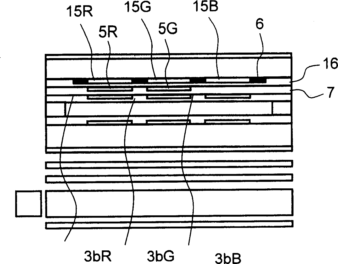
[0037] image 3 The cross-sectional structure of the display unit of this embodiment is schematically shown in FIG. The difference between this embodiment and Embodiment 1 is that a red color filter 15R is formed corresponding to the red area, a green color filter 15G is formed corresponding to the green area, and a blue color filter 15B is formed corresponding to the blue area. These color filters corresponding to each color region are formed using macromolecular group materials containing colorants or pigments to selectively transmit only the corresponding red wavelength range, green wavelength range or blue wavelength range. As shown in the drawings, the color filters 15R, 15G, and 15B in this embodiment are planarized using the second planarization layer 16 on which the red fluorescent material layer 5R and the green fluorescent material layer 5G are formed. A black matrix 6 is also formed in the gap between each color filter.

[0038] The efficiency of the red fluorescent ma...

Embodiment 3

[0041] Figure 4 The cross-sectional structure of the display unit of this embodiment is schematically shown in FIG. This embodiment is different from Embodiment 2 in that it does not provide a color filter for each color, but provides a blue mask 6B that cuts blue wavelengths (450-480 nm). The blue mask 6B only has holes in the blue area and exists in the red area and the green area. Therefore, the wavelength component in the blue region included in the light transmitted through the red region and the green region is cut by the blue mask 6B. That is, the equivalent operation of the red color filter 15R and the green color filter 15G of Embodiment 2 is obtained. According to this type of structure, the color filter layer can be eliminated, and it is possible to simplify the manufacturing process.

[0042] The blue mask 6B has a peak wavelength of 450 nm to 480 nm, and has a light transmission characteristic called blue visible light cut. For example, the mask is formed by diffusi...


PUM


Abstract

There is provided a color display unit having a wide range of color reproduction and low power consumption, with a simple structure, and without causing element deterioration. The display unit comprises light source means for generating blue light, a color conversion layer having a red color region for converting the blue light generated by the light source means to red light, a green color region for converting the blue light to green light, and a blue color region for transmitting the blue light as is, arranged on a flat surface, and a pixel switch structure for turning the blue light ON or OFF for each of the red color region, green color region and blue color region in response to an image signal.

Description

Technical field [0001] The present invention relates to a color image display unit used in a mobile information unit such as a mobile phone or a mobile computer or a large-scale image device such as a desktop computer or a home TV. Background technique [0002] Generally, a small and thin color liquid crystal display unit with low power consumption is generally used as a color image display unit in a mobile information unit such as a mobile phone or a mobile computer. High-brightness and low-power color liquid crystal display units are also rapidly developing in the field of large-scale image display devices such as desktop computers and home TVs. Compared with the case of conventional cold cathode tubes, since white LEDs are used as the illumination light source, these liquid crystal display units have obtained a smaller and thinner structure, reduced power consumption and extended lifespan. On the other hand, when a semi-transmissive liquid crystal display unit is used in a mob...

Claims


Application Information

Patent Timeline
IPC IPC(8): G02F1/1335G02B5/20G09F9/30
Inventor 栗原慎出岛范宏五十岚克之原光义
Owner SEIKO INSTR INC
Why Eureka
Try Eureka