Brush part for an electric toothbrush

An electric toothbrush, brush technology, applied in dentistry, cleaning teeth, medical science and other directions, to achieve the effect of low cost

Active Publication Date: 2006-12-20
BRAUN AG
View PDF3 Cites 14 Cited by
  • Summary
  • Abstract
  • Description
  • Claims
  • Application Information

AI Technical Summary

Problems solved by technology

The solution is structurally rather elaborate and therefore expensive

Method used


Image

  • Brush part for an electric toothbrush
  • Brush part for an electric toothbrush
  • Brush part for an electric toothbrush

Examples


Embodiment Construction

[0029] In the figures, identical parts are provided with the same reference numerals.
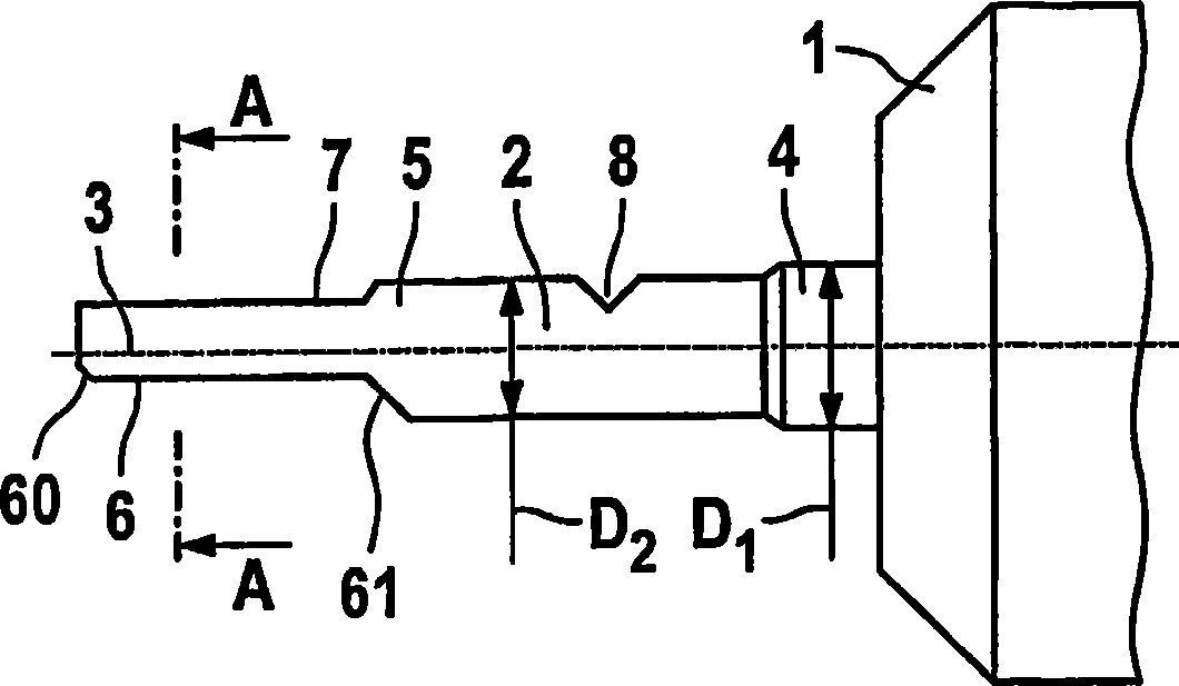
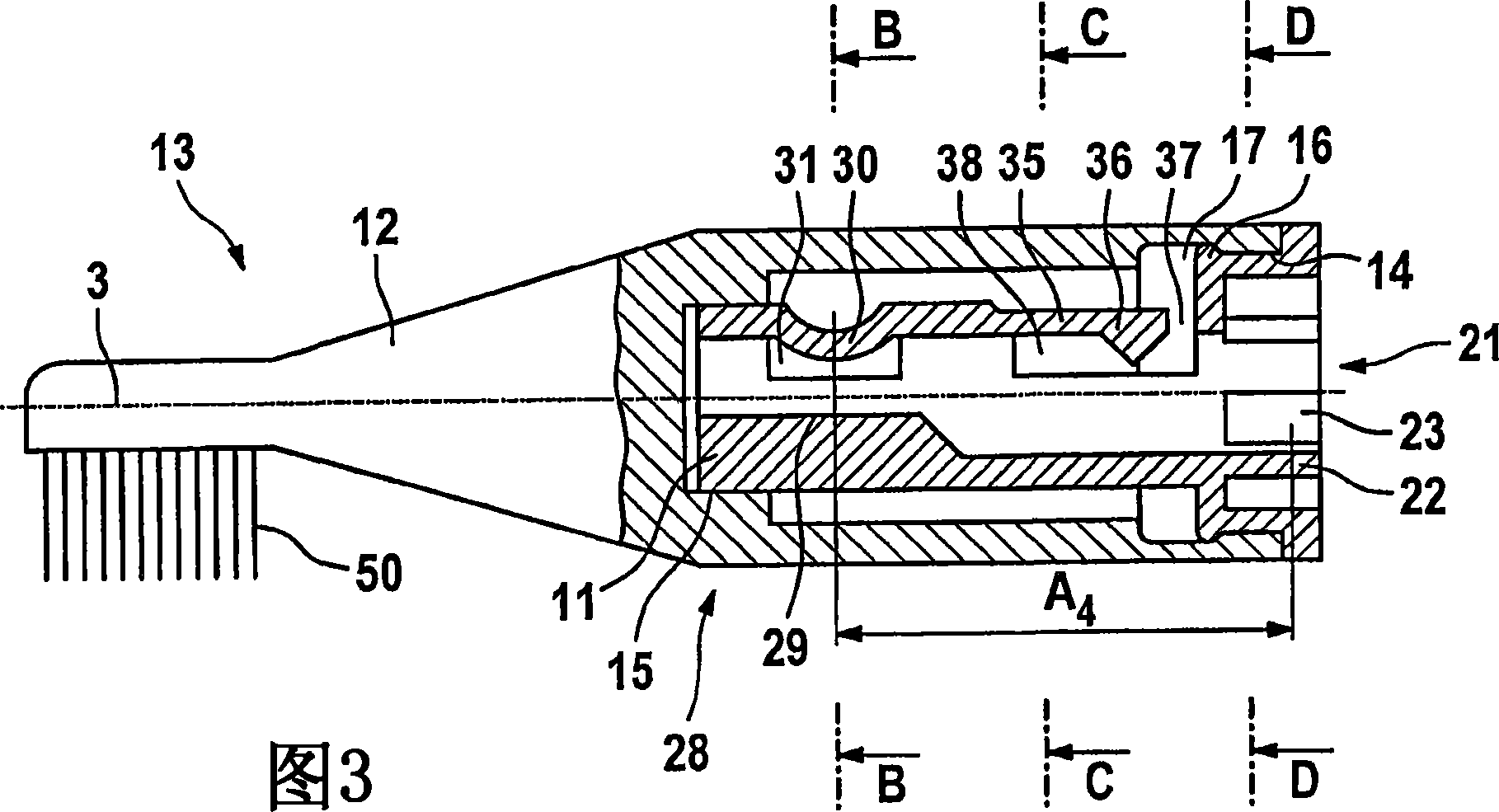
[0030] figure 1 The connection area of ​​the handle 1 of the electric toothbrush is shown, which is intended for connection with the brush part 13 according to the invention shown in FIG. 3 .

[0031] The handle 1 comprises a plastic casing and all parts required for operation, such as electric motor, transmission, accumulator or battery, controller and the like. These components are located in the housing and are not shown.

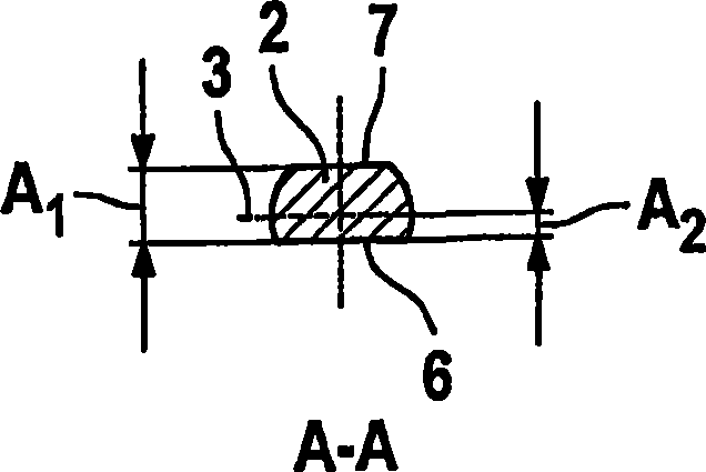
[0032] as in figure 1 As shown in , a shaft 2, in particular made of metal, protrudes directly from the handle 1, which shaft can oscillate torsionally about its longitudinal axis at a high frequency of about 260 Hz. That is to say, the shaft 2 is driven by an electric drive mechanism to vibrate. Other oscillating movements, for example along the axis 3 or combinations thereof, are also possible. This vibrational movement is directly transferred to the tufts 50 o...


PUM


Abstract

The invention concerns a brush part (13), which can be placed upon a shaft (2) of a handpiece (1) of an electric toothbrush and is designed so that it can be detached therefrom. Said brush part comprises a bristle area, a brush shank (12) and an attachment part (11) situated inside the brush shank (12). This attachment part (11) has a first spring element (35) and a second spring element (30) that act upon the shaft (2) when the brush part (13) is placed upon the shaft (2). This results in a play-free connection between the brush part and the shaft that enables the transmission of even high vibration frequencies.

Description

technical field [0001] The invention relates to a brush part according to the preamble of claim 1 and to an electric toothbrush with a handle and such a brush part. Background technique [0002] A replaceable brush part for an electric toothbrush is known from US 3,369,265. There are permanently arranged tufts of hair on the brush part. The end of the brush part for connecting with the handle has a hollow space in which two positioning grooves opposite to each other are provided, and the two positioning grooves are arranged in the same axial position. The connecting pin of the handle is engaged in the positioning groove, and the connecting pin is provided with a corresponding positioning protrusion. The end of the brush part intended to be connected to the handle is divided by two slots into two legs which, when the brush part is inserted into the stop finger, spread apart and allow a snap-in action. The end of the connecting pin engages in the flush-adjusted end of the h...

Claims


Application Information

Patent Timeline
Patent Type & Authority Applications(China)
IPC IPC(8): A61C17/22
CPCA61C17/222A61C17/22A61C17/3481
Inventor 诺贝特·舍费尔埃里克·艾森科尔布赖纳·恩格尔莫尔汉斯约尔格·赖克
Owner BRAUN AG
Why Eureka
Try Eureka