
A vertical hydraulic plunger mud pump

A hydraulic column and mud pump technology, applied in the field of vertical hydraulic plunger mud pumps, can solve the problems of low mechanical efficiency, unusable long-distance slurry transportation, high frequency of operation, etc., achieve volume and quality reduction, easy overload protection, The effect of large carrying capacity

Active Publication Date: 2016-08-24
山东国地水利土地勘察设计有限公司
View PDF4 Cites 0 Cited by
  • Summary
  • Abstract
  • Description
  • Claims
  • Application Information

AI Technical Summary

Problems solved by technology

There are various problems in the current mud pumps, such as large wear and short life of the slurry pump, high maintenance cost, and low head, which cannot be used for long-distance slurry transportation; diaphragm pumps are technically difficult and complex in structure , the pump is bulky, with a mechanical efficiency of about 85%. Under the same flow and pressure (head) conditions, the price of the entire diaphragm pump is the highest, which is several to dozens of times the price of other pumps. At the same time, due to the high frequency of operation, it is easy to wear The components and their annual operating costs are also high. Diaphragm pumps require the particle size of the conveyed materials to be less than 1 mm; oil isolation pumps have environmental pollution problems, and are low in intelligence and low in mechanical efficiency; water isolation pumps have two problems of water consumption and slurry mixing. Big problem; the pipeline of the water diaphragm pump does not have the function of automatic adjustment of pressure and flow rate; the high-pressure water spray pump has the problem of wasting water resources
The above pumps are not suitable for use in the pipeline sand transportation system

Method used


Image

  • A vertical hydraulic plunger mud pump

Examples


Embodiment Construction

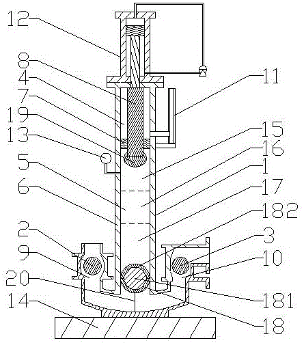
[0024] Accompanying drawing is the specific embodiment of the present invention. Such as figure 1 As shown, this kind of vertical hydraulic plunger mud pump includes a vertical plunger type mortar cylinder 1, which is installed on the base 14. The plunger type mortar cylinder 1 includes a cylinder body 6, a piston rod 8 and a replaceable annular The support seal ring 7, the piston rod 8 is a chrome-plated piston rod, and its lower end is equipped with a wear-resistant cap 19 made of ultra-high molecular weight polyethylene material. The annular support seal ring 7 is detachably fixed on the cylinder body 6 and sleeved on the piston. On the column 8, the annular support sealing ring 7 divides the inner cavity of the cylinder body 6 into an upper cavity 4 and a lower cavity 5, and a transparent open heat dissipation position indicator 11 is provided on the side wall of the upper cavity 4, and an open radiator It communicates with the upper cavity 4; the mud in the lower cavity ...


PUM


Abstract

The invention relates to a water conservation facility, and in particular, discloses a vertical hydraulic plunger slurry pump. The vertical hydraulic plunger slurry pump comprises a vertical plunger type mortar cylinder, wherein a hydraulic oil cylinder is connected to the inner upper side of the mortar cylinder; the output end of the hydraulic oil cylinder is connected with a piston column of the mortar cylinder; a wear resistant cap is arranged at the lower end of the piston column; a radiating position indicator is mounted on an upper cavity divided by an annular support sealing ring; a pressure sensor is arranged at the upper part of a lower cavity; and a side inlet and a side outlet are formed in the lower part, and are respectively provided with a one-way floating ball valve and a one-way gravity ball valve. The vertical hydraulic plunger slurry pump uses the hydraulic oil cylinder for pushing the piston column of the mortar cylinder to reciprocate so as to extrude clear water in the lower cavity to achieve the mortar extruding purpose, and has such characteristics as simple structure, convenience for operation, strong sand transportation capacity, high efficiency, low energy consumption, environmental protection and operation safety and reliability.

Description

(1) Technical field [0001] The invention relates to a water conservancy equipment facility, in particular to a vertical hydraulic plunger mud pump. (2) Background technology [0002] In the area along the Yellow River in Shandong Province, while promoting economic development, the coal resource mining industry has also brought many negative impacts, resulting in relatively serious geological and ecological damage. damage. In the subsidence area of ​​coal mining, where water accumulates all the year round, the area of ​​cultivated land is reduced, grain production is reduced or completely eliminated, and agricultural economic losses are huge. The houses in coal-pressing villages are cracked, tilted, and collapsed, which has seriously threatened the safety of people's lives and property in the subsidence area. [0003] The number of land-lost peasants caused by coal mining subsidence is increasing year by year, and the long-term livelihood of land-lost peasants is facing a s...

Claims


Application Information

Patent Timeline
Patent Type & Authority Patents(China)
IPC IPC(8): F04B15/02F04B9/103F04B51/00F04B53/14
Inventor 纪仁卿张恩铭万春和
Owner 山东国地水利土地勘察设计有限公司
Learn More