

Submount for light emitting/receiving device
一种光收发、用子座的技术,应用在电气元件、激光器零部件、半导体激光器的结构细节等方向,能够解决发光元件102散热性能不良、子座价格高、热传导性能差等问题,达到良好光传输性能的效果
- Summary
- Abstract
- Description
- Claims
- Application Information
AI Technical Summary
Problems solved by technology
Method used
Image

Examples
Embodiment Construction
[0085] Hereinafter, the present invention will be described in detail using the illustrated embodiments.
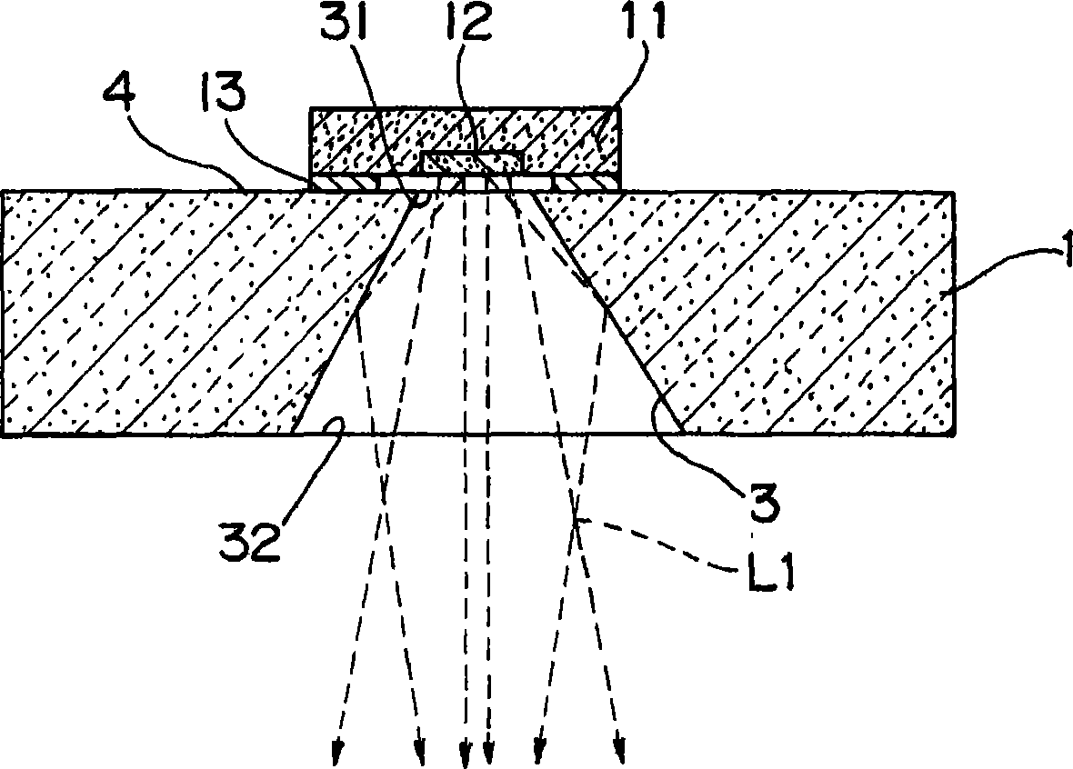
[0086] figure 1 It is a schematic cross-sectional view showing a submount for a light-emitting element according to an embodiment of the present invention.
[0087] This submount for light emitting elements has a submount main body 1, a through hole 3 formed by anisotropic etching on the submount main body 1, a light emitting element mounting surface 4 formed on the submount main body 1 and connected to the through hole 3. The element-side opening 31 of the hole 3 and the outer opening 32 formed on the outer surface of the submount main body 1 facing the light-emitting element mounting surface 4 . On the light-emitting element mounting surface 4 of the submount, a light-emitting element 11 is mounted via electrodes 13 , and the light-emitting element 12 of the light-emitting element faces the element-side opening 31 . That is to say, the light-emitting element 11 is el...
PUM
 Abstract
Description
Claims
Application Information