In-situ concrete plate

A cast-in-situ concrete slab and cast-in-situ technology are applied in the field of cast-in-place concrete slabs and can solve the problems of high cost and heavy weight of cast-in-situ concrete slabs.

Inactive Publication Date: 2006-12-27
邱则有
View PDF1 Cites 1 Cited by
  • Summary
  • Abstract
  • Description
  • Claims
  • Application Information

AI Technical Summary

Problems solved by technology

But, during the construction of this cast-in-place concrete slab, it is still necessary to use prefabricated thin slabs as formwork, the weight of the cast-in-place concrete slab is still relatively heavy, and the cost is still high.

Method used


Image

  • In-situ concrete plate
  • In-situ concrete plate
  • In-situ concrete plate

Examples


Embodiment Construction

[0071] The present invention will be further described below in conjunction with the drawings and embodiments.

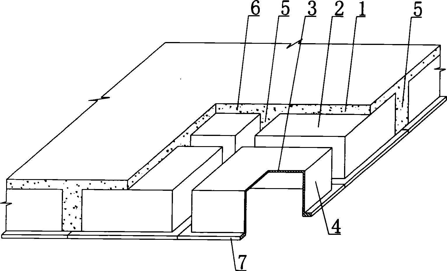
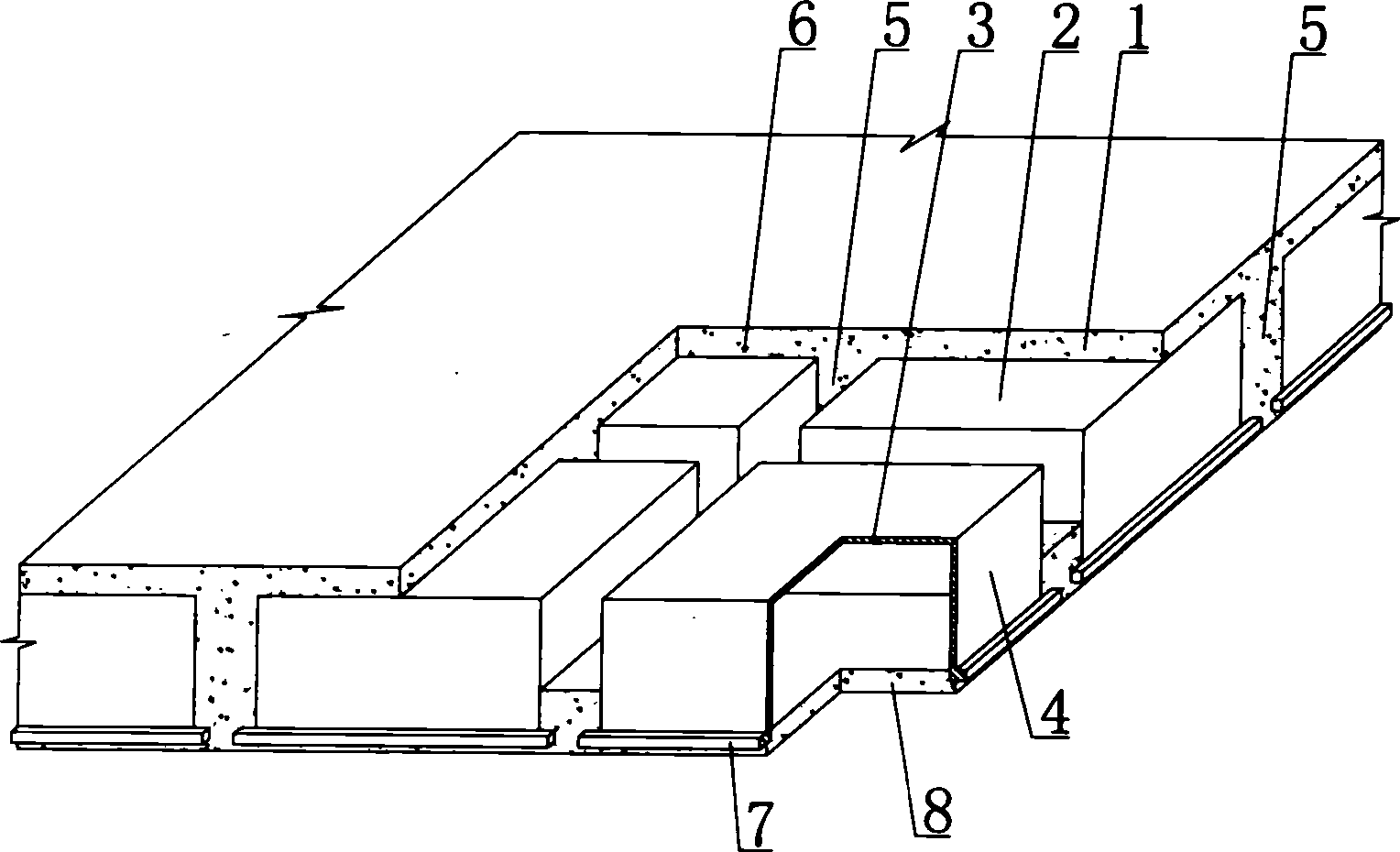
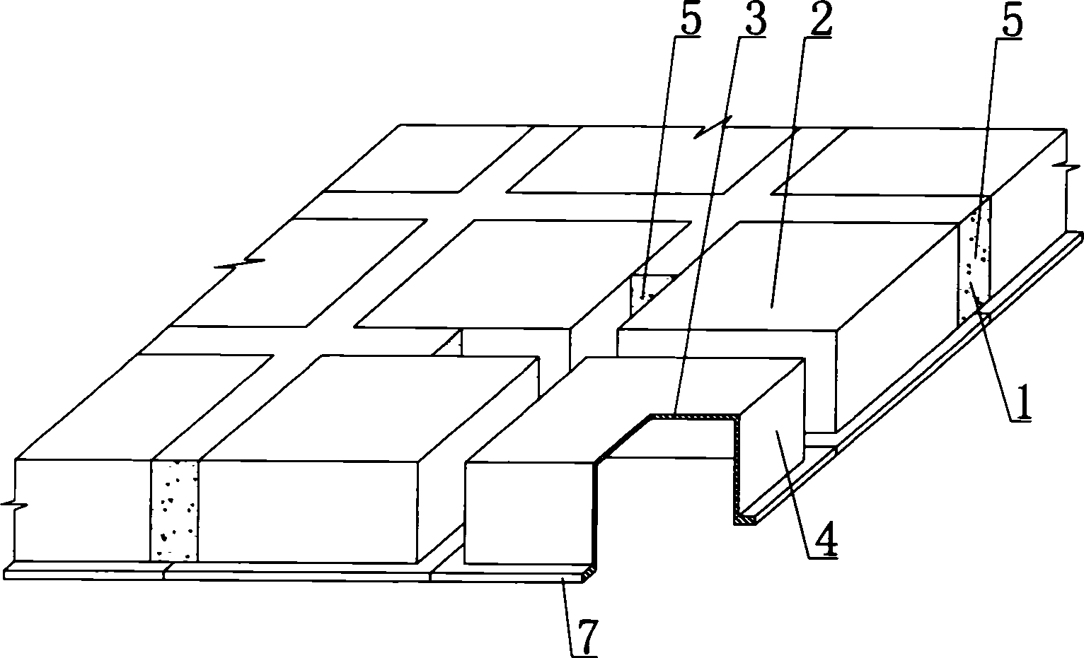
[0072] As shown in the drawings, the present invention includes reinforced concrete 1, a formwork member 2. The formwork member 2 includes an upper plate 3, a surrounding side wall 4, the upper plate 3 and the surrounding side wall 4 are surrounded by an open basin-shaped member, and the mold Between the surrounding side walls 4 of the shell member 2 are cast-in-place reinforced concrete ribs 5 formed by reinforced concrete 1, and on the upper plate 3 of the form member 2 is the cast-in-place reinforced concrete laminated layer 6 formed by reinforced concrete 1, and Connected to the cast-in-place reinforced concrete rib 5, the reinforced concrete 1 and the formwork member 2 are superimposed on each other to form a whole, characterized in that the surrounding side wall 4 has a toss 7 extending outward, and the toss 7 is thicker than the upper slab 3. The thickness of the...


PUM


Abstract

Disclosed is a cast-in-situ concrete slab, which comprises a reinforced-bar concrete (1) and shuttering members (2), the shuttering members (2) comprise an upper board (3) and peripheral side panels (4), the upper board (3) and the peripheral side panels (4) encloses an open basin shape component, cast-in-situ reinforced bar concrete ribs (5) formed by the reinforced-bar concrete (1) are disposed between the peripheral side walls (4) of the shuttering members (2), cast-in-situ reinforced bar concrete overlapping layers formed by the reinforced-bar concrete (1) are disposed above the upper board (3) of the shuttering members (2), and is connected to the cast-in-situ reinforced bar concrete ribs (5), the reinforced-bar concrete (1) and the shuttering members (2) are superposed into an integrity, characterized a projected edge (7) is arranged on the peripheral panel panels (4), the thickness of the projected edge is greater than the thickness of the peripheral panels, the invention can be applied to various cast-in-situ reinforced concrete or prestressed reinforcement concrete's storied-building roofings, house roofings, walls, foundation bedplates and bridges, especially for hollow flat slabs or dense rib slabs.

Description

(1) Technical field [0001] The invention relates to a cast-in-place concrete board. (2) Background technology [0002] At present, most buildings with brick-concrete structure and frame structure use prefabricated hollow slabs as floor slabs. This kind of floor slab has the advantages of fast construction speed and low cost, but because there is no firm connection between two adjacent prefabricated hollow slabs , Only use cement mortar to fill the gaps, so not only the integrity is poor and it is not conducive to earthquake resistance, but also cracks and water seepage often occur in the gaps, causing great inconvenience and psychological pressure to the residents. In order to solve the above problems, many buildings have adopted the method of cast-in-place concrete slabs (hollow, solid). Although the cast-in-place slab solves the problems of earthquake resistance and cracking, a large number of templates are used during construction. This not only increases the cost, but also sl...

Claims


Application Information

Patent Timeline
IPC IPC(8): E04B1/16E04B5/36E04B5/48E04C5/00E04G15/06
Inventor 邱则有
Owner 邱则有
Why Eureka
Try Eureka