Constant velocity buffering exhaust valve

An exhaust valve and valve body technology, applied in the direction of lift valve, valve details, valve device, etc., can solve the problems of pipeline burst and poor exhaust, and achieve the effect of reducing vibration and reasonable structure design.

Inactive Publication Date: 2006-12-27
杨硕
View PDF0 Cites 5 Cited by
  • Summary
  • Abstract
  • Description
  • Claims
  • Application Information

AI Technical Summary

Problems solved by technology

Its characteristics are: when the gas in the pipeline enters the exhaust valve, the buoy hanging on one end of the buoy rod in the valve body loses buoyancy and falls, causing the small valve core at the other end of the buoy rod to rise, open the small valve port, and close the small exhaust The exhaust port on the cap allows the gas to enter the hydraulic cylinder through the conduit, and the diaphragm assembly in the hydraulic cylinder is affected by the air pressure to open the cover plate on the large exhaust port on the valve body to achieve high-speed exhaust, and when water enters the exhaust valve After the body, the buoy rises, the small valve core descends, the small valve port is closed, and the exhaust port on the exhaust cap is opened at the same time, so

Method used


Image

  • Constant velocity buffering exhaust valve

Examples


Example Embodiment

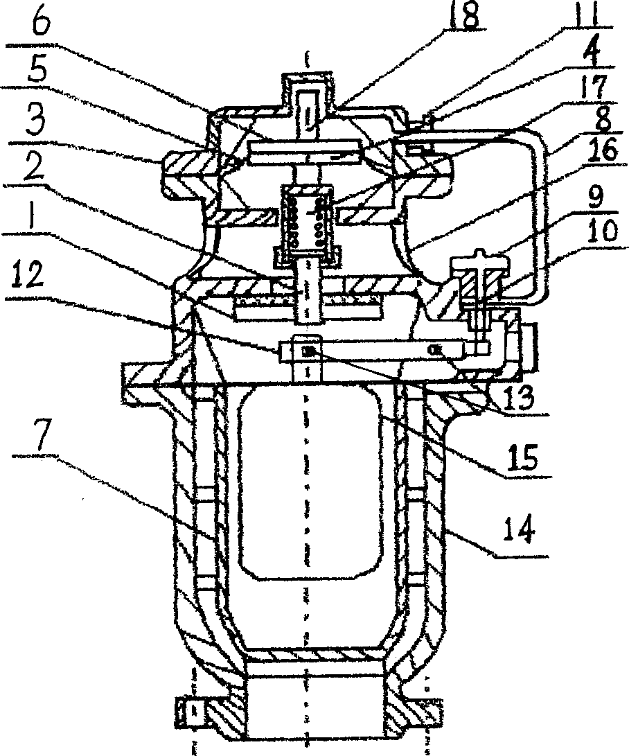
[0010] The present invention will be further described below in conjunction with the drawings.

[0011] according to figure 1 As shown, the present invention is mainly composed of a lower valve body 14, a middle valve body 16, a buoy 15, a buoy rod 12, a small valve core 10, a cover plate 1, a lower rod 2, an upper slide rod 18, a pressure sensitive spring 17 and a diaphragm 5. The middle valve body 16 is connected to the lower valve body 14 by bolts. The valve cover 3 is installed on the upper end of the middle valve body 16. The valve cover 3 is characterized in that the float 15 is located in the protective tube 7 in the lower valve body 14. Inside, the buoy 15 is hinged with one end of the buoy rod 12, and the other end of the buoy rod 12 is hinged on the middle valve body 16 through a main shaft installed on the middle valve body 16, and is installed on the middle valve body 16 through a small groove on itself. Lifting of the small spool 10; the cover plate 1 is connected wit...


PUM


Abstract

The invention relates to a constant-speed buffer discharge valve, which comprises a lower valve body, middle valve body, float rod, small valve pin, cover plate, lower slide rod, upper slide rod, compress sensitive spring, film, and valve cover, wherein the float is hinged with one end of float rod; the float rod via the axle of middle valve body is hinged to the middle valve body; the float is inside the protective cylinder inside the lower valve body; the cover plate is connected to the lower sliding rod; the upper sliding rod, the film lower compress rod, the film and the film upper compress plate are integrated, to form control element with the compress sensitive spring; the film is compressed via valve cover on the middle valve body; the tube via current-limit connector is through to the inner chamber of hydraulic cylinder on the middle valve body and the valve cover; the small discharge cap is screwed on the middle valve. The invention is characterized in that: it uses float lever to control the switch of large gas outlet, whose open degree changes along the pressure of tube, to realize full-automatic stable-pressure ventilation.

Description

technical field [0001] The invention relates to a pipeline exhaust and water hammer protection device, in particular to a constant-speed buffer exhaust valve generally used on water supply pipelines. Background technique [0002] Existing exhaust valves are divided into three types. That is, the full-pressure high-speed exhaust valve, single-port exhaust valve, high-speed exhaust valve and the combination of these two valves are called double-port exhaust valves. The exhaust valve is generally installed on the pressured water supply pipeline buried underground. The function is to discharge the gas in the pipeline to prevent the pipeline from bursting. [0003] In order to discharge gas under any conditions, the exhaust port of a single-port exhaust valve is generally very small, which cannot meet the needs of a large pipeline for large-scale exhaust. Its working principle is that when the gas in the main pipeline enters the exhaust valve, the floating ball loses its buoyan...

Claims


Application Information

Patent Timeline
IPC IPC(8): F16K1/00F16K31/126F16K31/26
Inventor 杨硕杨玉思
Owner 杨硕
Why Eureka
Try Eureka