Plate type air preheater
An air preheater and plate-type technology, applied in lighting and heating equipment, combustion methods, indirect carbon dioxide emission reduction, etc., can solve the problems of heat transfer efficiency and pressure drop, easy dust accumulation, long-term operating cost, heat transfer Low efficiency and other problems, to achieve the effect of solving the problem of equipment dust accumulation, long-term reliable operation, and reducing equipment weight
- Summary
- Abstract
- Description
- Claims
- Application Information
AI Technical Summary
Problems solved by technology
Method used
Image
Examples
Embodiment 1
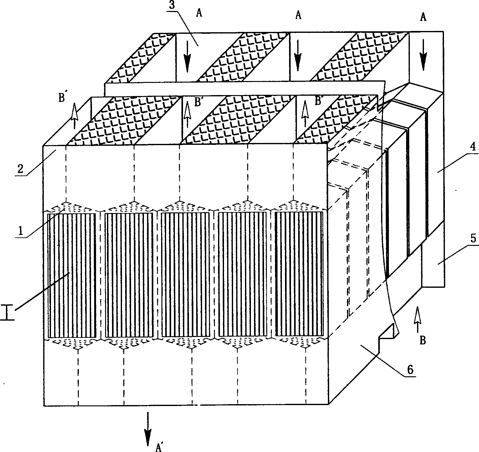
[0032] Example 1: A plate-type air preheater for a one-layer plate bundle assembly.
[0033] structured as figure 1 As shown, it includes: a box body 1, heat exchange components and air and flue gas inlet and outlet pipe boxes, the plate heat exchange components arranged in the box body 1, and the plate heat exchange components are combined into a plate by a layer of plate bundle modules 4 A bundle assembly 7, the upper end of the plate bundle assembly 7 communicates with the flue gas inlet pipe box 3 and the air outlet pipe box 2, the lower end of the plate bundle assembly communicates with the smoke outlet pipe box 6 and the air inlet pipe box 5, the plate bundle The module 4 is composed of corrugated plates, and the air in the plate bundle module 4 and the flue gas passage are closed passages in opposite directions.
[0034] The shape of the corrugated sheet is hexagonal, with triangular distribution guide areas 401 and 403 on the top and bottom respectively, and a rectang...
Embodiment 2
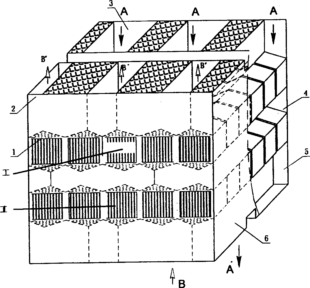
[0040] Example 2: Plate Air Preheater for Two-layer Plate Bundle Assembly
[0041] Such as figure 2 As shown: including: box body 1, heat exchange components and air and flue gas inlet and outlet pipe boxes, the plate heat exchange components arranged in the box body 1, the plate heat exchange components are composed of upper and lower two-layer plate bundle modules 4 Combined into plate bundle assemblies I and II, the upper end of the plate bundle assembly I communicates with the flue gas inlet pipe box 3 and the air outlet pipe box 2, and the lower end of the plate bundle assembly II communicates with the flue gas outlet pipe box 6 and the air inlet pipe box 5 , the plate bundle module 4 is composed of stacked corrugated plates, and the air and flue gas channels in the plate bundle module 4 are closed passages in opposite directions.
[0042]The shape of the corrugated sheet is hexagonal, with triangular distribution guide areas 401 and 403 on the top and bottom respective...
Embodiment 3
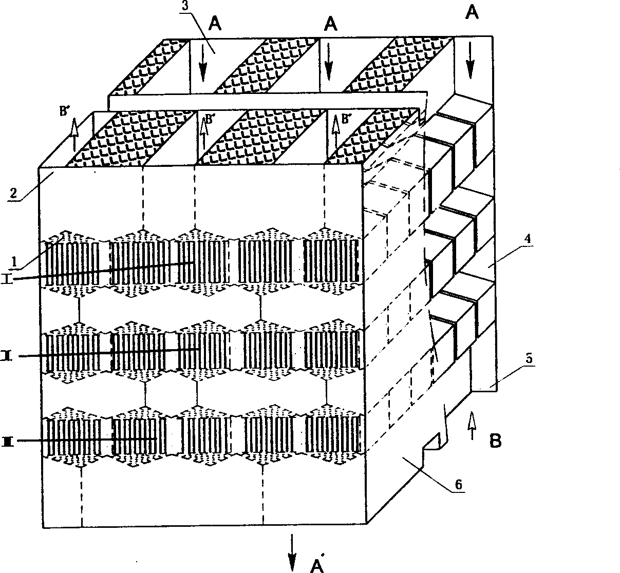
[0049] Example 3: Air preheater for three-layer plate bundle assembly.
[0050] Such as image 3 As shown: the box body 1 is provided with upper, middle and lower three-layer plate bundle module layers, the upper layer is the plate bundle module layer I of the high temperature section, the middle layer is the plate bundle module layer II of the medium temperature section, and the lower layer is the plate bundle module layer of the low temperature section Layer III, the structure and arrangement of the board bundle module 4 are the same as those in Embodiments 1 and 2 and will not be described in detail. The materials used: the upper plate bundle module I adopts high temperature resistant 354 alloy material, which is suitable for medium heat exchange above 1000°C; the medium temperature section plate bundle module 4 adopts 304 alloy steel, which is suitable for medium heat exchange around 700°C; the low temperature section plate bundle module 4 adopts Below 170-180°C, low-temp...
PUM
 Abstract
Description
Claims
Application Information
 - R&D
- Intellectual Property
- Life Sciences
- Materials
- Tech Scout
- Unparalleled Data Quality
- Higher Quality Content
- 60% Fewer Hallucinations
Browse by: Latest US Patents, China's latest patents, Technical Efficacy Thesaurus, Application Domain, Technology Topic, Popular Technical Reports.
© 2025 PatSnap. All rights reserved.Legal|Privacy policy|Modern Slavery Act Transparency Statement|Sitemap|About US| Contact US: help@patsnap.com


