Method of manufacturing a cooling plate and a cooling plate manufactured with this method

A cooling plate and plate body technology, which is applied in the field of manufacturing cooling plates, can solve the problems of difficult removal of casting sand, improper molding, and insufficient firmness of cooling pipes, and achieve reliable production, quality, economical savings, and stable quality.

Inactive Publication Date: 2006-12-27
PAUL WURTH SA
View PDF5 Cites 13 Cited by
  • Summary
  • Abstract
  • Description
  • Claims
  • Application Information

AI Technical Summary

Problems solved by technology

Disadvantages of this method are: it is difficult to remove the casting sand from the cooling pipes, and / or the cast iron cooling pipes are often poorly formed or not strong enough
This method requires expensive large size shrink fit equipment for cast iron body and steel pipe dimensions

Method used


Image

  • Method of manufacturing a cooling plate and a cooling plate manufactured with this method
  • Method of manufacturing a cooling plate and a cooling plate manufactured with this method
  • Method of manufacturing a cooling plate and a cooling plate manufactured with this method

Examples


specific Embodiment approach

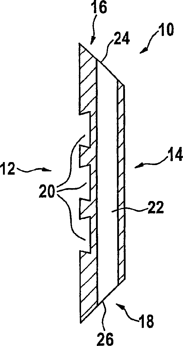
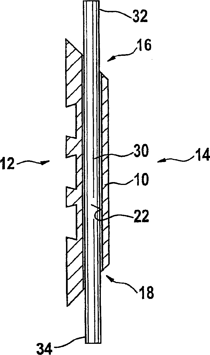
[0057] figure 1 Shown is a sheet metal body 10 according to the invention for producing cooling panels (also called stave walls) which are arranged inside the walls of a metallurgical furnace, for example a blast furnace. The plate body 10 has a front 12 , a back 14 and four peripheral surfaces. Two of the four peripheral surfaces are identified with reference numerals 16, 18, while the other two peripheral surfaces are in figure 1 is not visible in the cross-sectional view. The two peripheral surfaces 16 , 18 are inclined towards the rear side 14 of the plate body 10 . The front face 12 exposed inside the blast furnace is advantageously provided with grooves 20 which increase the cooling surface and improve the adhesion of the refractory lining. The reference numeral 22 designates a straight cylindrical channel 22 which penetrates the sheet metal body 10 below the front face 12 to form openings 24 , 26 on the peripheral faces 16 and 18 . The cross-section of the channel i...

example

[0063] Tube diameter: 69,9-70,1mm (at 20°C)

[0064] Channel diameter: 70,3-70,8mm (at 20°C)

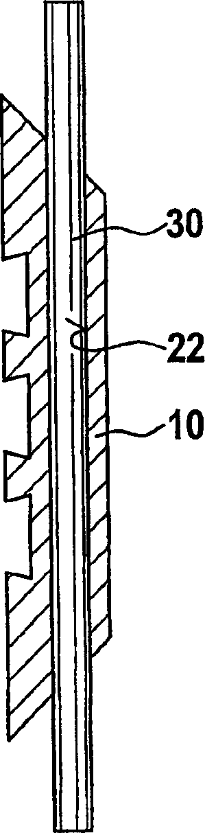
[0065] Rolling the plate by 1 mm is sufficient to achieve a press fit of the tube 30 in the channel 22 . The cross-section of the tube 30 becomes slightly oval.

[0066] Since there is a certain upper limit to the extent to which the entire plate body 10 can be rolled, additional steps may be applied as pre- or post-processing in order to support the press fit obtained by rolling the plate body 10 . A number of such additional steps are described below.

[0067] In the first additional step, as in Figure 6 As shown, channels 22 and tubes 30 are dimensioned in cross-section such that both plate 10 and tubes 30 have a radial clearance of tubes 30 in channels 22 at ambient temperature (ie, a positive tolerance). After the tube 30 is inserted into the channel 22 of the plate body 10 , the conical expansion head 40 is pulled through the tube 30 by the hydraulic cylinder 42 . This ex...


PUM

PropertyMeasurementUnit
diameteraaaaaaaaaa
diameteraaaaaaaaaa

Abstract

A method of manufacturing a cooling plate comprises following steps: providing a metallic plate body (10) with a front face (12), a rear face (14) and at least one channel (22) extending through the metallic plate body beneath the front face; inserting with radial clearance a metallic tube (30) into the channel (22) so that both tube ends (32, 34) protrude out of the channel (22); and achieving a press fit of the tube (30) within the channel (22) by shrinking the section of the channel (22) by means of a metal-forming process applied to the plate body (10).

Description

technical field [0001] The invention relates to a method of producing a cooling plate and a cooling plate produced by this method. Background technique [0002] Cooling plates, also known as "staves", have been used in blast furnaces for hundreds of years. Cooling plates are arranged on the inside of the furnace wall and have internal coolant pipes connected to the cooling water circuit of the blast furnace. The surface of the cooling plate facing the interior of the blast furnace may be lined with a refractory material. The cooling water connection pipe ends are arranged on the back side of the cooling plate and lead out of the furnace wall in a sealed manner. The cooling channels of several cooling plates are connected in series and are connected to the cooling water circuit of the blast furnace via the ends of these connecting pipes leading out of the furnace wall. [0003] Until a few years ago, most cooling plates in blast furnaces were cast iron cooling plates. The...

Claims


Application Information

Patent Timeline
Patent Type & Authority Applications(China)
IPC IPC(8): C21B7/10F27B1/24F27D1/12F27D9/00F28D7/00F28F1/14
CPCF28D7/0041C21B7/10F27D2009/0018F27B1/24F27D1/12F27D2009/0045F28F1/14F27D9/00F27D2009/0062Y10T29/49863Y10T29/49874
Inventor 罗伯特·施梅勒尼古拉斯·穆塞尔盖伊·蒂伦
Owner PAUL WURTH SA
Why Eureka
Try Eureka