Bored concrete pile foundation distributing optical fiber sensing detecting method and system

A technology of distributed optical fiber and detection method, which is applied in the direction of using optical devices to transmit sensing components, infrastructure engineering, foundation structure tests, etc., can solve the problem of failure to reflect pile body defects and stress concentration conditions, difficult bearing capacity and pile Integrity of the body, difficulty in installing distributed optical fibers, etc., to avoid low survival rate, save detection costs, and improve monitoring efficiency

Active Publication Date: 2007-01-03
SUZHOU NANZEE SENSING TECH
View PDF0 Cites 58 Cited by
  • Summary
  • Abstract
  • Description
  • Claims
  • Application Information

AI Technical Summary

Problems solved by technology

However, the point measurement method generally has the following limitations: (1) It is a discontinuous measurement, which is easy to miss, and sometimes cannot reflect the pile body defects and stress concentration; It is easy to fail in the test, and it is affected by various factors such as zero point drift, high installation and maintenance costs, and reduced precision due to electromagnetic field interference during the test, which leads to data loss or distortion in the actual test; (3) In order to improve the detection accuracy, the installation Too many sensors will affect the structure and bearing capacity of the pile body because of too many lead wires; (4) It is difficult to analyze the quality of the pile body and the interaction between the pile and the layers of the stratum with sporadic point data
[0006] The distributed optical fiber sensing detection method for the cast-in-place pile foundation has not been adopted, because it is difficult to fix and reliably install the distributed optical fiber on the cast-in-place pile foundation
This makes it difficult to analyze the bearing capacity and integrity of the pile with the BOTDR method

Method used


Image

  • Bored concrete pile foundation distributing optical fiber sensing detecting method and system
  • Bored concrete pile foundation distributing optical fiber sensing detecting method and system
  • Bored concrete pile foundation distributing optical fiber sensing detecting method and system

Examples


Embodiment Construction

[0031] (1) Optical fiber packaging

[0032] Place the optical fiber and the carrier according to the length of the pile to be tested. The length of each fiber should be twice the length of the pile plus 5m. Spread the grooved carrier on the workbench, inject glue into the groove, then press into the single-mode nylon optical fiber to smooth it out, and use blowing to speed up the drying. After the glue is completely dry, wrap the optical fiber with a reel. During the winding process, carefully check whether there is any unglued part of the optical fiber, and reapply it in time.

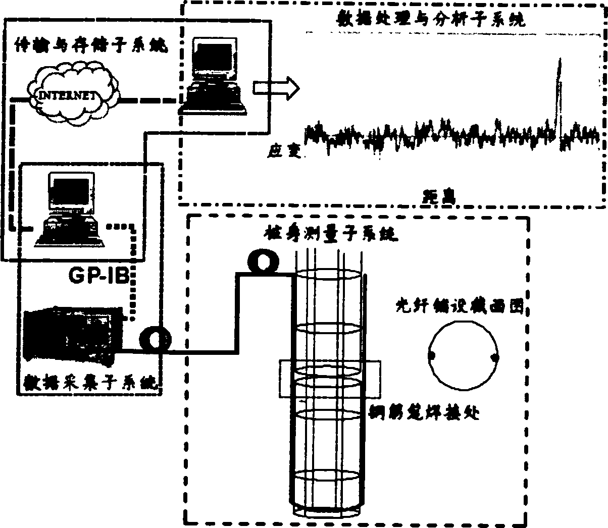
[0033] (2) On-site laying

[0034] There are currently two main methods of optical fiber laying: one is to paste the optical fiber on the structure under test with a special or special adhesive, which is mainly used for the monitoring of built structures; the other is to implant the optical fiber In structures such as reinforced concrete, this method is mainly used for safety and quality monitoring ...


PUM


Abstract

The present invention relates to a distributed optical-fibre sensing detection method for cast-in-place pile foundation. It is characterized by that it utilizes the sensing property of optical fibre for strain, so that the optical fibre can be implanted in the cast-in-place pile. When the concrete is solidified or loaded externally, said concrete and its peripheral concrete can produce synchronous deformation, its produced strain extent is the strain valve of said pile-body concrete. The invented sensing technique is a distributed data acquisition, namely, it can obtain the strain data of every point of pile-body. Said invention can utilize these data to implement detection and analysis of cast-in-place pile.

Description

1. Technical field [0001] The invention belongs to the technical field of geotechnical engineering monitoring and detection and the technical field of detection based on distributed optical fiber sensing; in particular, it relates to a distributed optical fiber sensing detection method for cast-in-place pile foundations. 2. Background technology [0002] Cast-in-place pile is a type of pile foundation that can meet the load-bearing requirements of various strata. Its load-bearing characteristics and force distribution with the surrounding rock and soil can be detected by pre-embedded related sensing elements during field static load tests. Sure. The pile detection in the current static load test is mainly point measurement, that is, pre-embedded strain gauges such as steel bar gauges, strain gauges or buried stress gauges, displacement gauges, etc. on the reinforcement cage of the pile body. By measuring the strain value of each point, the pile Body strain and stress distri...

Claims


Application Information

Patent Timeline
Patent Type & Authority Applications(China)
IPC IPC(8): E02D33/00G01D5/353
Inventor 施斌张巍王宝军刘杰王小明索文斌魏广庆朴春德刘春隋海波张丹朱友群胡盛李科
Owner SUZHOU NANZEE SENSING TECH
Why Eureka
Try Eureka