Whole-metal stator screw drilling tool

A screw drilling tool and all-metal technology, which is applied to drilling equipment, earthwork drilling, and driving devices for drilling in boreholes, etc., can solve the problems that screw drilling tools cannot meet production requirements, and achieve improved rock-carrying capacity and heat dissipation performance , heat deformation uniform effect

Inactive Publication Date: 2007-01-03
SOUTHWEST PETROLEUM UNIV
View PDF0 Cites 27 Cited by
  • Summary
  • Abstract
  • Description
  • Claims
  • Application Information

AI Technical Summary

Problems solved by technology

In the past 10 years, with the emergence of a large number of horizontal wells, radial wells, and lateral horizontal wells, especiall

Method used


Image

  • Whole-metal stator screw drilling tool
  • Whole-metal stator screw drilling tool
  • Whole-metal stator screw drilling tool

Examples


Embodiment Construction

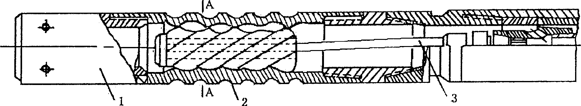
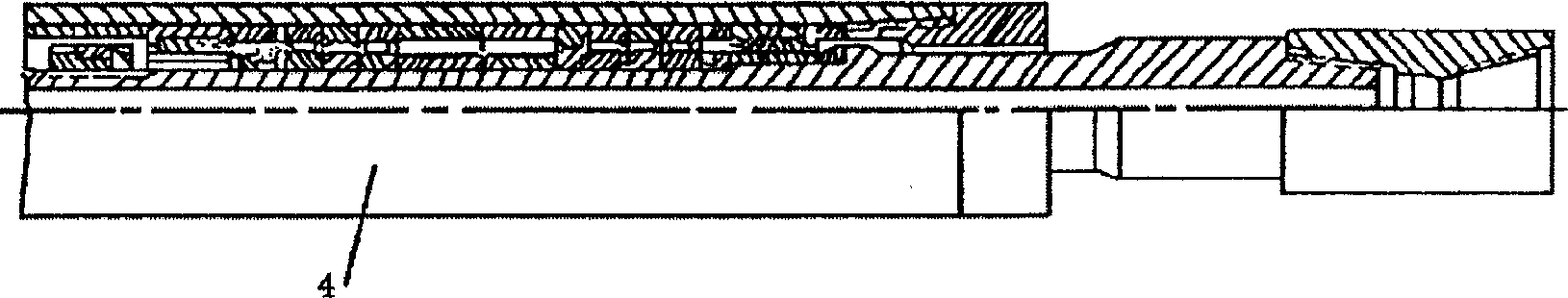
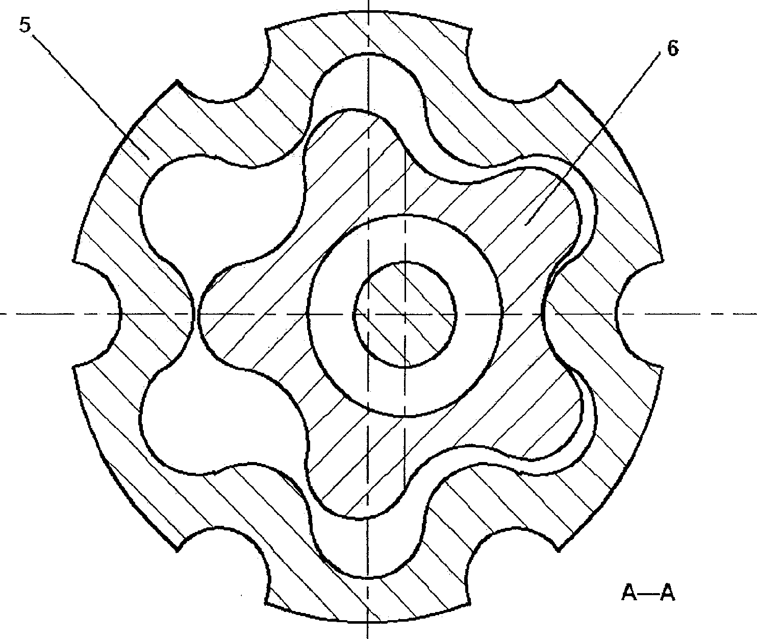
[0010] See figure 1 , figure 2 , image 3 . The screw drilling tool of the present invention is composed of a bypass valve assembly 1, a screw motor assembly 2, a flexible cardan shaft assembly 3, a drive shaft assembly 4, and the like. The motor is a positive displacement power machine driven by a drilling fluid, which consists of an all-metal stator 5 and a rotor 6. The rotor 6 is a hollow steel screw plated with abrasion-resistant material, and the stator 5 is a steel tube with spiral curved surfaces inside and outside. The upper end of the rotor 6 is connected with the cardan shaft, and the lower end of the cardan shaft is connected with the transmission shaft. The stator 5 is fixed, and the rotor 6 makes a planetary movement around the axis of the stator 5 under the driving of the pressure drilling fluid. The cardan shaft transmits the autotransmission part of the planetary motion of the rotor 6 to the transmission shaft, so that the transmission shaft rotates as a fixed sha...


PUM


Abstract

The present invention relates to an al-metal stator screw drill. It is formed from successively-connected by-pass valve assembly, screw rod motor assembly, flexible universal shaft assembly and driving shaft assembly. The screw rod motor assembly includes stator and rotor positioned in the stator cavity, and the described stator is made up by using metal material, the internal wall and external wall of said stator respectively have spiral grooves, the interior of said stator and the rotor are formed into a spiral curved cavity, and the exterior of said stator can allow the drilling fluid to flow through.

Description

Technical field [0001] The invention relates to a screw drilling tool for petroleum drilling. Background technique [0002] Screw motor is currently the most widely used downhole power drilling tool. It is mainly used for deflecting and twisting directional wells and horizontal wells, and part of it is also used in vertical well reverse or sidetracking operations. The United States began to develop screw drilling tools in the mid-1950s and used them for production in 1962. Different manufacturers produced Dina drilling tools (Smith company), Navitas drilling tools (Christensen company) and Persian drilling tools. The basic principles are based on volume. Type motor. At present, the stators of conventional screw drills are all made of rubber, which has low pressure bearing capacity, is not wear-resistant, and cannot withstand high temperatures. Only the internal structure and technical parameters are slightly different. In the past 10 years, with the emergence of a large number of...

Claims


Application Information

Patent Timeline
IPC IPC(8): E21B4/02
Inventor 张茂韩传军宋晓琴田家林
Owner SOUTHWEST PETROLEUM UNIV
Why Eureka
Try Eureka