Eureka AIR delivers breakthrough ideas for toughest innovation challenges, trusted by R&D personnel around the world.

Piston type gas combustion turbine engine

A gas turbine and engine technology, applied in gas turbine installations, machines/engines, mechanical equipment, etc., can solve the problems of mass (large weight, high manufacturing difficulty, slow response speed, etc.) fast effect

Inactive Publication Date: 2007-01-03
李志文
View PDF0 Cites 8 Cited by
  • Summary
  • Abstract
  • Description
  • Claims
  • Application Information

AI Technical Summary

Problems solved by technology

[0002] There are still many problems in the existing gas turbine engine: large mass (weight), high noise, high fuel consumption, complex structure, high manufacturing difficulty, high cost, low efficiency, and low response speed (power change rate) Slow, most of them can only be used in large quantities on airplanes and are difficult to use in large quantities on water and land vehicles such as automobiles, motorcycles, trains, and ships

Method used


Image

  • Piston type gas combustion turbine engine
  • Piston type gas combustion turbine engine
  • Piston type gas combustion turbine engine

Examples


Embodiment 1

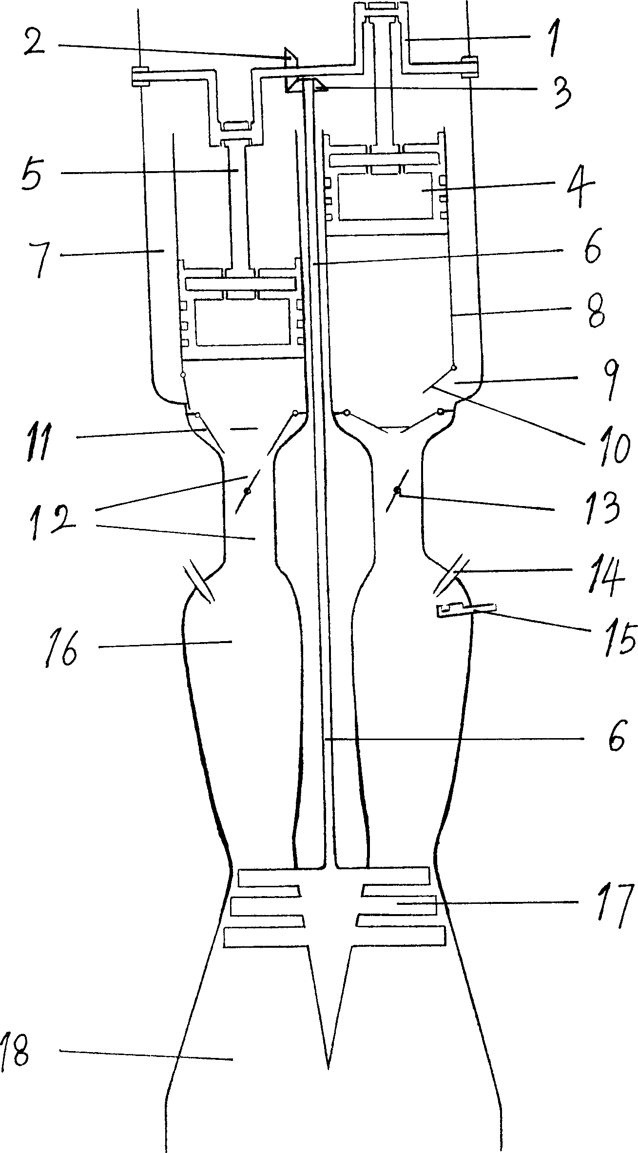
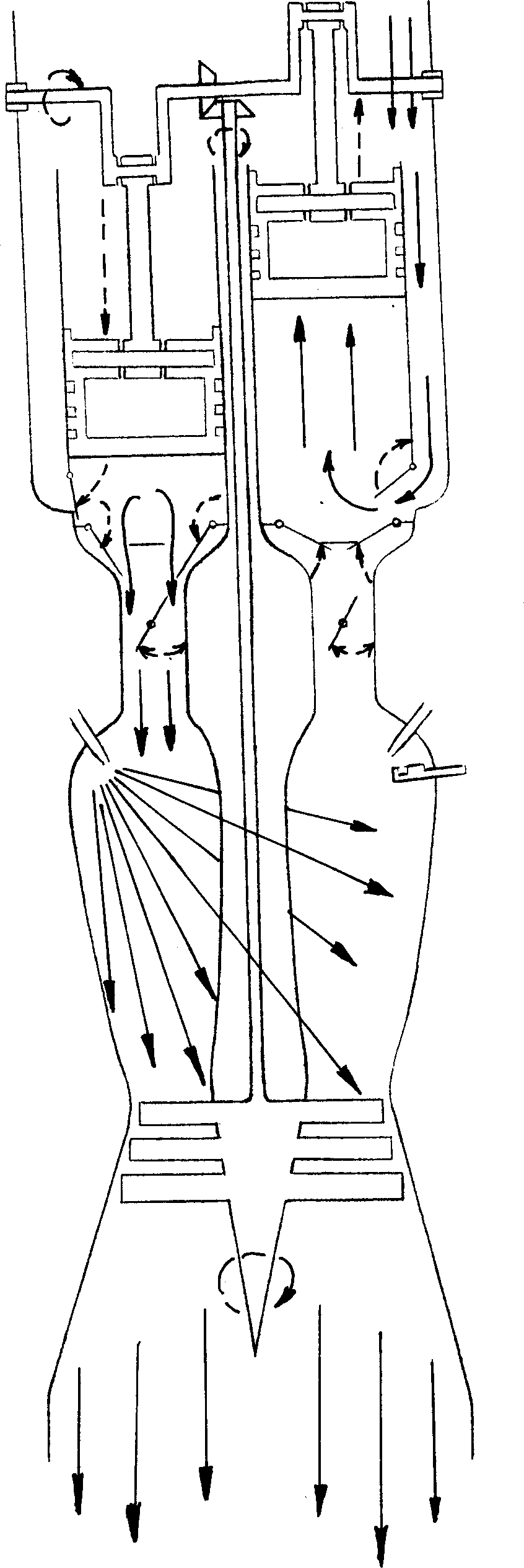
[0026] Two pistons are used as compressors, the structure can refer to figure 1 , The bevel gear (2) on the crankshaft (1) meshes with the bevel gear (3) fixed on the upper end of the turbine shaft (6), the lower end of the turbine shaft (6) is connected with the turbine (17), and the crankshaft (1) is connected with The piston connecting rod (5) is connected, and the piston connecting rod (5) is connected with the piston (4). The piston (4) can reciprocate freely in the cylinder (cylinder) (8), and the outer wall of the lower end of the cylinder (8) There is an intake port (9), an intake valve (10) is provided on the intake port (9), an air supply valve (11) is provided at the lower end of the cylinder block (8), and the end of the cylinder block (8) is connected with the compressed air (high pressure air) ) The upper end of the passage (12) is connected, the lower end of the compressed air passage (12) is connected with the combustion chamber (16), the compressed air passage (1...

Embodiment 2

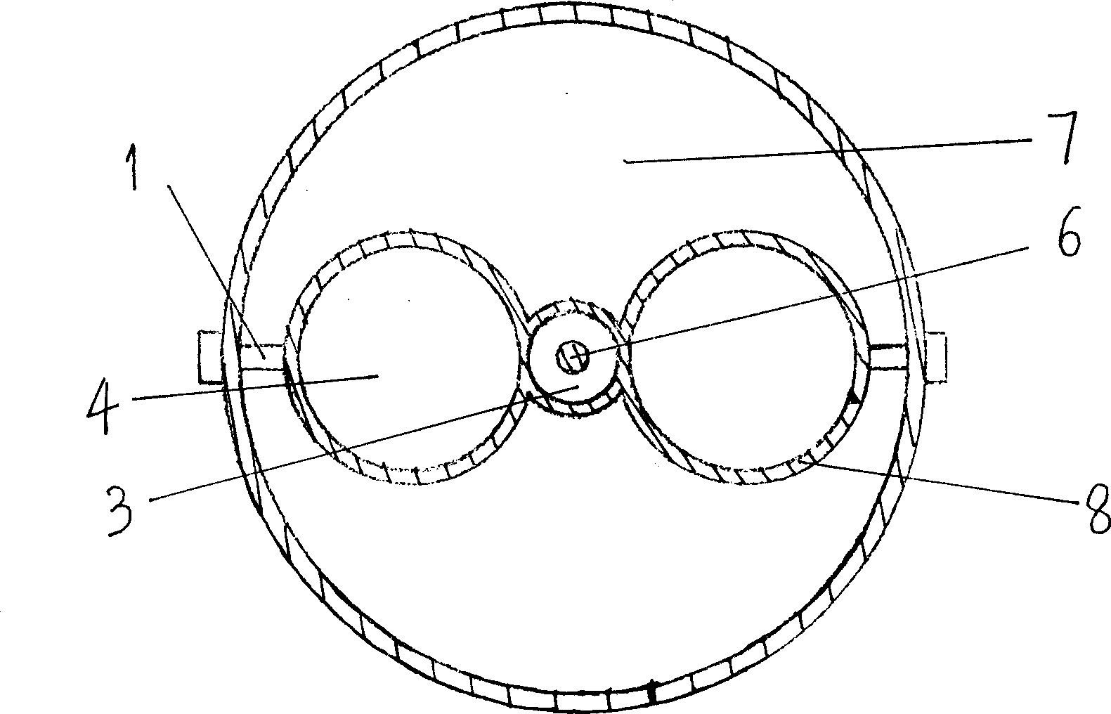
[0029] The structure of this embodiment is basically the same as that of Embodiment 1. The main difference is that this embodiment uses four pistons as a compressor, and two more pistons are added than Embodiment 1, and a crankshaft and two pistons are added correspondingly. Connecting rods, two cylinders, three gears, a gear shaft (19), two compressed air channels, two throttles and two fuel nozzles, four cylinders are joined together, and each crankshaft is connected with two pistons Rod connection, four piston connecting rods are connected to the four pistons respectively, that is, a crankshaft controls the reciprocating motion of the two pistons, please refer to Figure 6 , Figure 7 with Figure 8 . When the engine is started, the two crankshafts are driven by the turbine shaft (6) through the gear shaft (19), and the bevel gear (3) on the upper end of the turbine shaft (6) meshes with the bevel gear (2) on the gear shaft (19) , The gear (20) on the gear shaft (19) meshes wit...


PUM


Abstract

The present invention relates to a piston type gas turbine engine. It is characterized by that it adopts piston instead of air compressor of traditional gas turbine engine, the crankshaft is connected with piston connecting rod, the piston connecting rod is connected with piston, said piston can be reciprocally moved in the cylinder body, on lower end wall of said cylinder body an air inlet valve is set, the tail end of said cylinder body is equipped with an air supply valve, in the compressed air channel a throttle valve is set, the conical gear on the crankshaft is meshed with the conical gear in the upper end of turbine rotating shaft, and the lower end of said turbine, rotating shaft is connected with turbine.

Description

Technical field: [0001] The invention relates to a gas turbine engine, in particular to a gas turbine engine using a piston as a compressor. Background technique: [0002] Existing gas turbine engines still have many problems: high quality (weight), high noise, high fuel consumption, complex structure, high manufacturing difficulty, high cost, low efficiency, and response speed (rate of power change) Slow, most of them can only be used in large quantities on airplanes but difficult to use on land and water vehicles such as cars, motorcycles, trains, and ships. Summary of the invention: [0003] The present invention provides a piston gas turbine engine that can overcome or improve the shortcomings described in the background art. [0004] The general structure of the present invention can refer to figure 1 , Including crankshaft (1), bevel gears (2), bevel gears (3), pistons (4), piston connecting rods (5), turbine shafts (6), intake ducts (internal ducts) (7) , Cylinder block ...

Claims


Application Information

Patent Timeline
Patent Type & Authority Applications(China)
IPC IPC(8): F02C3/055
Inventor 李志文
Owner 李志文
Why Eureka
Eureka Blog
Learn More