Light assembling structure for optical fiber gyro-space application

A fiber optic gyroscope and combined structure technology, applied in Sagnac effect gyroscopes and other directions, can solve the problems of low reliability, difficult to maintain volume, etc., and achieve the effects of high reliability, firm and stable instruments, and increased heat conduction area.

Inactive Publication Date: 2007-01-03
BEIHANG UNIV
View PDF0 Cites 6 Cited by
  • Summary
  • Abstract
  • Description
  • Claims
  • Application Information

AI Technical Summary

Problems solved by technology

[0006] The technology of the present invention solves the problem: it overcomes the disadvantages of low reliability, difficult maintenance and large size of the traditional mechanical gyroscope due to the moving parts, and the light fiber optic gyroscope combination provided has compact structure, small size, light weight and low thermal resistance. Small size, high reliability, good heat transfer performance and vibration performance, very suitable for attitude control of space vehicles

Method used


Image

  • Light assembling structure for optical fiber gyro-space application
  • Light assembling structure for optical fiber gyro-space application
  • Light assembling structure for optical fiber gyro-space application

Examples


Embodiment Construction

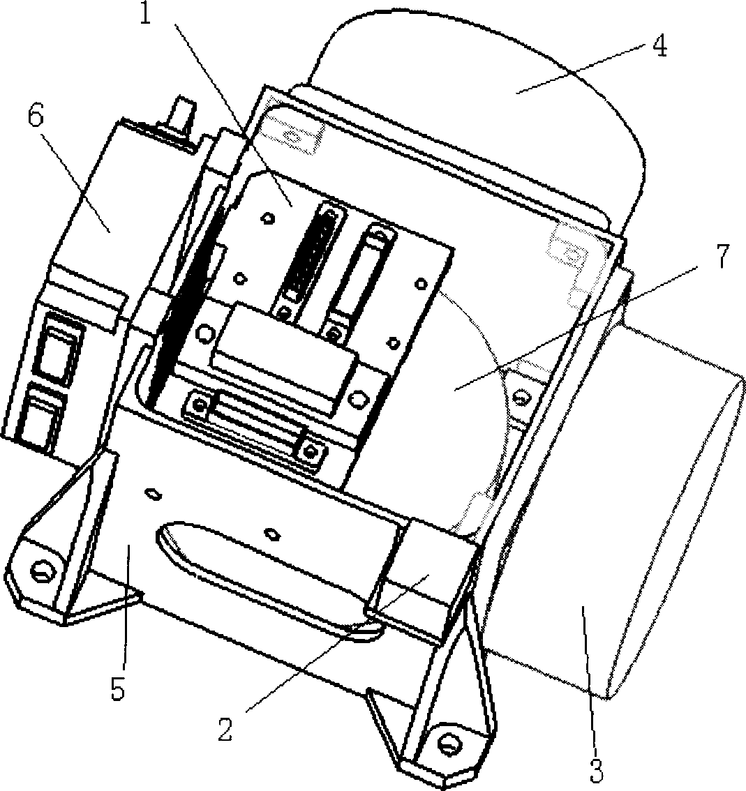
[0021] Such as figure 1 As shown, the x-axis gyro 3 and the y-axis gyro 4 are respectively installed on the outside of the side of the main body 5. The z-axis gyro 7 is located under the connector board 1 and installed on the inner side of the bottom plate of the main body 5. The x-axis gyro 3 and the y-axis gyro 4 The z-axis gyroscopes 7 are perpendicular to each other, forming an orthogonal system that respectively senses the angular velocities of the x-axis, y-axis, and z-axis in the orthogonal coordinate system. By integrating the angular velocities of the three axes, the position information of the spacecraft can be obtained to determine the satellite Posture information. The bottom surfaces of the three fiber optic gyroscopes are in full contact with the mounting surface of the body 5 to increase the heat conduction area between the lower surface of the gyro and the body, reduce the thermal resistance, and improve the heat transfer performance; at the same time, in order to...


PUM


Abstract

Optical fiber peg-top space applied light combination structure has a perpendicular configuration reality and its side faces are vertical with the underside. The outside of two side faces and the inside of underside are the fixing plane to three peg-tops. The rest side faces use to fix the electrical source box and cube mirror. The three peg-tops are perpendicular setting, and the peg-top of x axis and y axis is fixed on the outside of the reality side faces, the peg-top of z axis is fixed on the inside of the reality underside. Their fixing surfaces contact completely to increase the heat exchange area of the peg-top to reduce the heat resistance effectively. The three joining pieces connecting with peg-tops fix on one joining piece plane and put the three joining piece planes into one to connect with the jack of the reality connecting with system. The three peg-tops can debug alone and this is fit for fixing and maintenance the optical fiber peg-top. It is suitable for the gesture controlling of the space aerocraft with small volume, light weight, little heat resistance, high reliability security, well diathermancy.

Description

Technical field [0001] The invention relates to a light fiber optic gyroscope combined structure suitable for space applications. Background technique [0002] In recent years, fiber optic gyroscopes (FOG) have received much attention due to their potential advantages and application prospects, and have become the leading device in the new generation of inertial guidance and measurement systems. With the in-depth research of fiber optic gyroscopes, people have gradually solved various key problems of fiber optic gyroscopes, and the performance of fiber optic gyroscopes has been continuously improved. Now the fiber optic gyroscope has achieved integration and digitization. The zero drift of the fiber optic gyroscope developed abroad has reached 0.001° / h, the calibration factor stability is better than a few ppm, and the measurement accuracy has reached 0.0003° / h. The fiber optic gyroscope as a whole can fully meet the needs of various applications in space. [0003] Based on the a...

Claims


Application Information

Patent Timeline
Patent Type & Authority Applications(China)
IPC IPC(8): G01C19/72
Inventor 肖文刘德文杜新政韩艳玲李瑞
Owner BEIHANG UNIV
Why Eureka
Try Eureka