Supercharge Your Innovation With Domain-Expert AI Agents!

Rotating joint for the mutual connection of two shaft ends in particular in the drive train of a motor vehicle

A technology for motor vehicles and drive trains, applied in the direction of couplings, elastic couplings, mechanical equipment, etc., can solve complex problems, shorten the service life and prevent rotation.

Inactive Publication Date: 2007-01-03
SGF SUDDEUTE GELENKSCHEIBENFAB
View PDF3 Cites 7 Cited by
  • Summary
  • Abstract
  • Description
  • Claims
  • Application Information

AI Technical Summary

Problems solved by technology

The operational performance of such a centering device integrated in a flexible disc depends on the fact that the embedded metal parts remain precisely positioned relative to each other during the vulcanization of the flexible disc, which is complex

Method used


Image

  • Rotating joint for the mutual connection of two shaft ends in particular in the drive train of a motor vehicle
  • Rotating joint for the mutual connection of two shaft ends in particular in the drive train of a motor vehicle
  • Rotating joint for the mutual connection of two shaft ends in particular in the drive train of a motor vehicle

Examples


Embodiment Construction

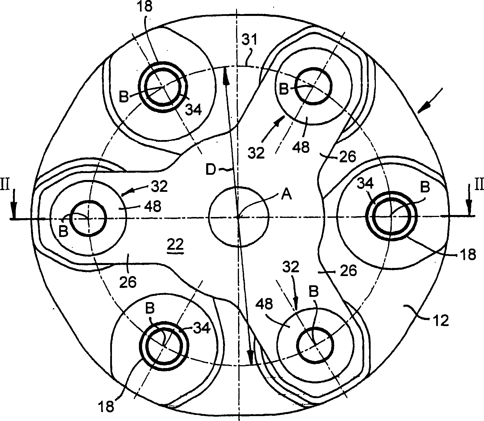
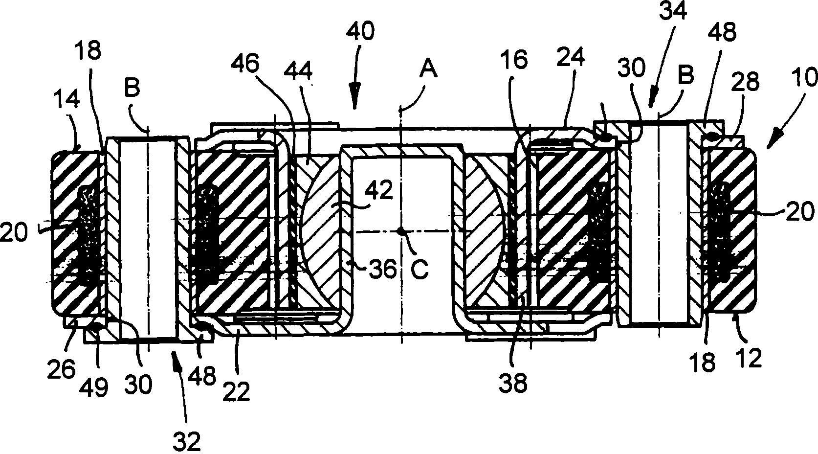
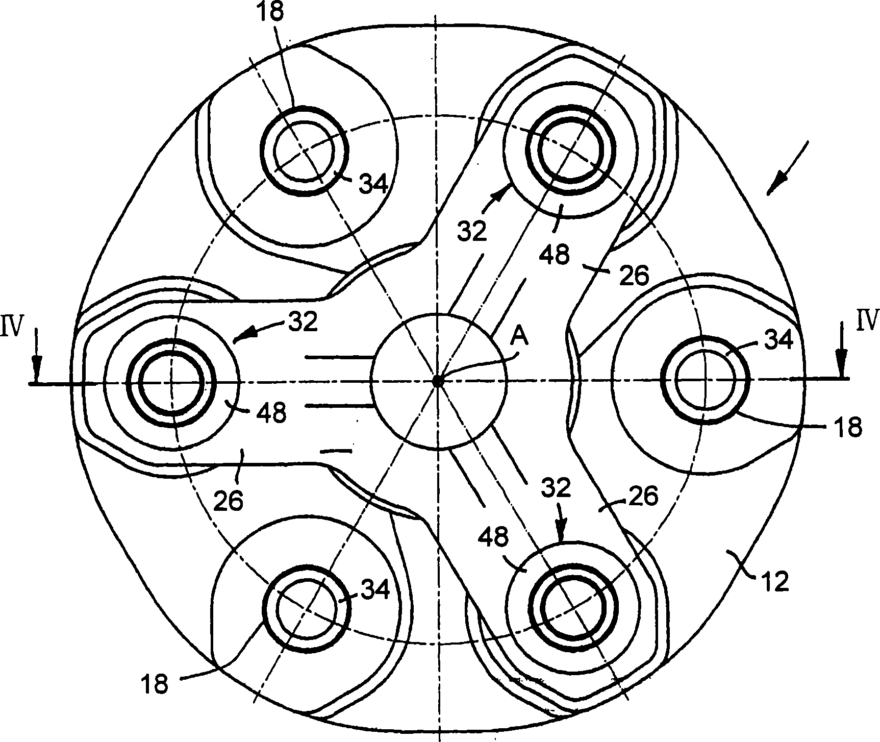
[0019] exist figure 1 with figure 2 The flexible coupling shown in has as the basic torque transmitting part a flexible disk 10, which is basically made of rubber or some other rubber-like elastic material, and is formed to be substantially rotationally symmetrical with respect to a central axis A, and is formed by a vertical Delimited by two substantially planar end faces on this axis, a first end face 12 and a second end face 14 , have a circular central recess 16 . Six cylindrical sleeves 18 are vulcanized into the flexible disk 10, the axis B of these sleeves being parallel to the central axis A and arranged at uniform angular intervals of 60° on a common reference circle. Wrapped around each sleeve 18 and adjacent sleeves 18 are coil-shaped flexible inserts 20 which are likewise vulcanized into the material of the flexible disc 10 . In this sense, the flexible disk 10 is conventional in design.

[0020] The flexible disk 10 is arranged between two end plates, a first ...


PUM


Abstract

The invention relates to a joint doughnut (10), made from a rubbery elastic material, with a central axis (A), at least two first and two second connection bodies (32, 34), each for fixing to a shaft end, arranged alternately with the axes thereof (B) parallel to the central axis (A) and around the above at angular separations from each other. Flexible inserts (20) are embedded in the joint doughnut (10) which extend around adjacent connection bodies (32, 34). A centering device (40) is provided for the mutual centering of both shaft ends, comprising a first and a second front plate (22, 24) which can be connected to either front face (12, 14) of the joint doughnut (10), centered relative to each other, such as to pivot about the joint centre (C), lying on the central axis (A). Independent of the subsequent fixing thereof to the first or second shaft end, the first connection body (32) is fixed to the first front plate (22) and the second connection body (34) is fixed to the second front plate (24) in a rigid and non-rotating manner.

Description

technical field [0001] The invention relates to a flexible coupling according to the preamble of claim 1 . Background technique [0002] Flexible couplings of this type are known from DE 2 255 533 A1 and DE 3 942 432 C1. According to DE 2 255 533 A1, inside the flexible disk, a three-pointed star-shaped support is arranged centrally with respect to the reference circle of the flexible disk. Flexible inserts in the form of grouped rings rest on the corners of the star-shaped support. The support body has a central hole for receiving a centering pin fastened to one of the two shaft ends interconnected by a flexible disc. Since the predetermined shape of the ring set can only be observed with limited precision for manufacturing reasons, and this shape changes during operation (depending, for example, on the transmitted torque), a centering that meets current requirements cannot be achieved by means of the support. Also there is a risk that the flexible insert will be damaged...

Claims


Application Information

Patent Timeline
Patent Type & Authority Applications(China)
IPC IPC(8): F16D3/78F16D3/50
CPCF16D3/50F16D3/78F16D3/62
Inventor 约阿希姆·罗特约瑟夫·鲍尔
Owner SGF SUDDEUTE GELENKSCHEIBENFAB
Features
  • R&D
  • Intellectual Property
  • Life Sciences
  • Materials
  • Tech Scout
  • Unparalleled Data Quality
  • Higher Quality Content
  • 60% Fewer Hallucinations
Learn More