Supercharge Your Innovation With Domain-Expert AI Agents!

Electromechanically actuated valve control based on a vehicle electrical system

A vehicle electrical and electric drive technology, applied in the direction of electrical control, non-mechanically actuated valves, spark ignition controllers, etc., can solve problems such as reducing the overall efficiency of the system

Active Publication Date: 2011-05-18
FORD GLOBAL TECH LLC
View PDF2 Cites 0 Cited by
  • Summary
  • Abstract
  • Description
  • Claims
  • Application Information

AI Technical Summary

Problems solved by technology

Furthermore, even if there is enough power, if too many electrically driven valves are working, the overall efficiency of the system will decrease

Method used


Image

  • Electromechanically actuated valve control based on a vehicle electrical system
  • Electromechanically actuated valve control based on a vehicle electrical system
  • Electromechanically actuated valve control based on a vehicle electrical system

Examples


Embodiment Construction

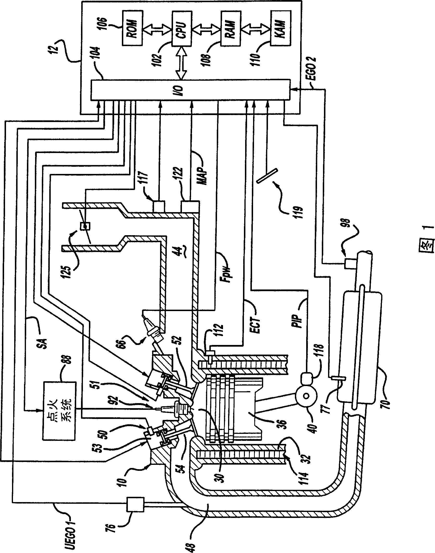
[0049] Referring to FIG. 1 , an internal combustion engine 10 controlled by an electronic engine controller 12 includes a plurality of cylinders, one of which is shown in FIG. 1 . Internal combustion engine 10 includes combustion chamber 30 , cylinder walls 32 and piston located therein and connected to crankshaft 40 . Combustion chamber 30 communicates with intake manifold 44 and exhaust manifold 48 via intake valve 52 and exhaust valve 54 , respectively, as shown. Each intake and exhaust valve is controlled by an electromechanically controlled valve coil and armature assembly 53 . The armature temperature is determined by means of a temperature sensor 51 . The valve position is determined by a position sensor 50 . In another example, each valve actuator of valves 52 and 54 has a position sensor and a temperature sensor.

[0050] Intake manifold 44 is also shown coupled to fuel injector 66 which supplies liquid fuel in an amount proportional to the pulse width of the FPW s...


PUM


Abstract

A method to control electromechanical valves are controlled to improve the possibility starting an engine based on a vehicle electrical system. The method comprising: operating the electrically actuated valve in the cylinder under a first condition of the vehicle electrical system; and deactivating operation of said electrically actuated valve in said cylinder under a second operating condition of the vehicle electrical system.

Description

technical field [0001] The present invention relates to methods of controlling valves in internal combustion engines, and more particularly, to methods of controlling electromechanically actuated valves based on the state of a vehicle's electrical system. Background of the invention [0002] A method of controlling intake and exhaust valve operation during engine operation is described in US Patent No. 6,332,446. This method uses electromechanically actuated valves to control engine vibrations caused by cylinder deactivation. The method activates at least one of the plurality of cylinders in a cylinder deactivation mode in which intake stroke, combustion stroke, and exhaust stroke are inhibited. The method then controls the pressure in each inactive cylinder operating in the cylinder deactivation mode. [0003] Once the strokes for each cylinder have been set by the method described above, the valve opening and closing timings are determined by retrieving a map based on ac...

Claims


Application Information

Patent Timeline
Patent Type & Authority Patents(China)
IPC IPC(8): F01L9/04F02D13/02F16K31/06F01L9/20F01L1/38F01L13/00F02N19/00
CPCF01L1/38F02D41/064F02D2200/503F02D2013/0292Y02T10/18F02D2041/0012F02N19/004F01L13/0005F02D13/0203F02D13/0253F02D41/021F02P5/1506F02D41/0002F02D13/06F01L9/04F02D41/0082Y02T10/42Y02T10/12Y02T10/40F01L9/20
Inventor 刘易斯·J·唐纳德米歇里尼·O·约翰
Owner FORD GLOBAL TECH LLC
Features
  • R&D
  • Intellectual Property
  • Life Sciences
  • Materials
  • Tech Scout
  • Unparalleled Data Quality
  • Higher Quality Content
  • 60% Fewer Hallucinations
Learn More