Switching power supply apparatus

a technology of switching power supply and power supply device, which is applied in the direction of electric variable regulation, process and machine control, instruments, etc., can solve the problems of reducing the efficiency of rated load, high cost of high-voltage switching element, and large conduction loss, so as to reduce the number of switching operations per unit time, reduce the cost of high-voltage switching element, and prevent the effect of switching loss

Active Publication Date: 2012-12-13
MURATA MFG CO LTD
View PDF9 Cites 19 Cited by
  • Summary
  • Abstract
  • Description
  • Claims
  • Application Information

AI Technical Summary

Benefits of technology

[0038]In the light load state such as the standby time, an operation is performed in the standby mode where the switching frequency is reduced and an operation is performed in the current-discontinuous mode. Accordingly, the number of switching operations per unit time is reduced, the switching loss is significantly reduced and prevent, and hence, it is possible to achieve high efficiency.
[0039]Since, in the light load state, the second switching element (high side FET) is put into an on-state for enough time to absorb a surge voltage occurring in the first switching element Q1 when the first switching element (low side FET) is turned off, it is possible to reduce a withstand voltage required for the first switching element Q1.
[0040]Since an intermittent oscillation operation is avoided, there is no increase in an output ripple, and the voltage accuracy of the output voltage is excellent.
[0041]Since an oscillation halt time period in such a way as intermittent oscillation does not exist, a response characteristic with respect to the rapid change of a load is excellent.
[0042]Since, in the light load state such as the standby time, an electric power conversion operation is performed due to almost only the operation of the first switching element (low side FET), it is possible to reduce the drive loss of an FET.
[0043]The above and other elements, features, steps, characteristics and advantages of the present invention will become more apparent from the following detailed description of the preferred embodiments with reference to the attached drawings.

Problems solved by technology

In general, since the cost of a high-voltage switching element is high and a voltage drop at the time of conduction is large, a conduction loss is large.
As a result, there exists a problem that efficiency in the rated load is lowered.
In the second type, since the intermittent oscillation operation is adopted, there exists a problem that the ripple of an output voltage is large or the period of intermittent oscillation existing in an audible frequency range results in making a sound.
Furthermore, since, in an oscillation time period, two FETs operate, there exists a problem that the drive loss of the FET is large or an output response characteristic with respect to the rapid fluctuation of an output load is poor.
In the third type, since a switching frequency becomes high while the power consumption of the switching control circuit or the like is reduced at the standby time, a switching loss becomes large, and the effect of reducing power consumption is small.

Method used


Image

  • Switching power supply apparatus
  • Switching power supply apparatus
  • Switching power supply apparatus

Examples


first preferred embodiment

[0070]A switching power supply apparatus according to a first preferred embodiment will be described with reference to FIG. 2 to FIG. 7.

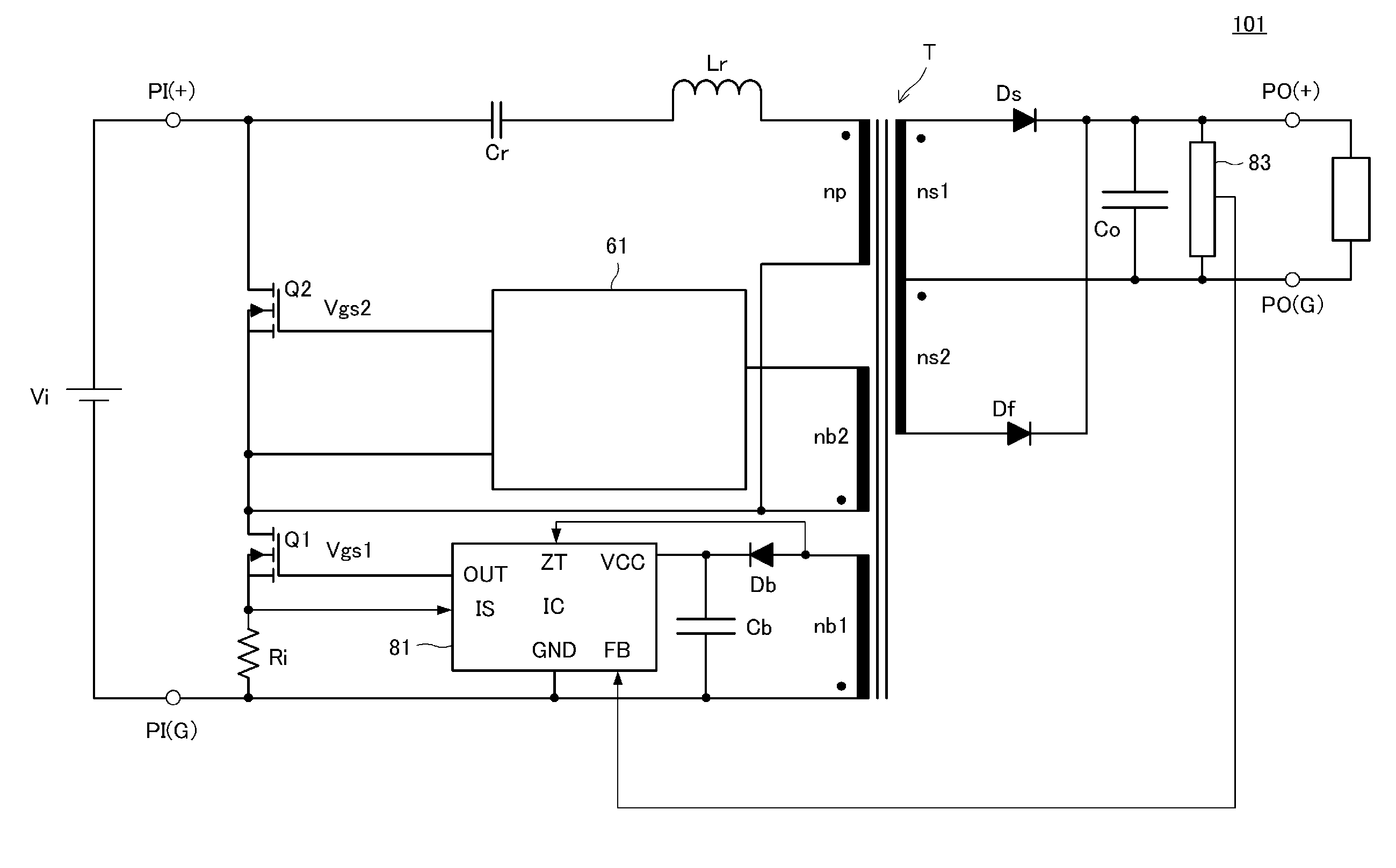
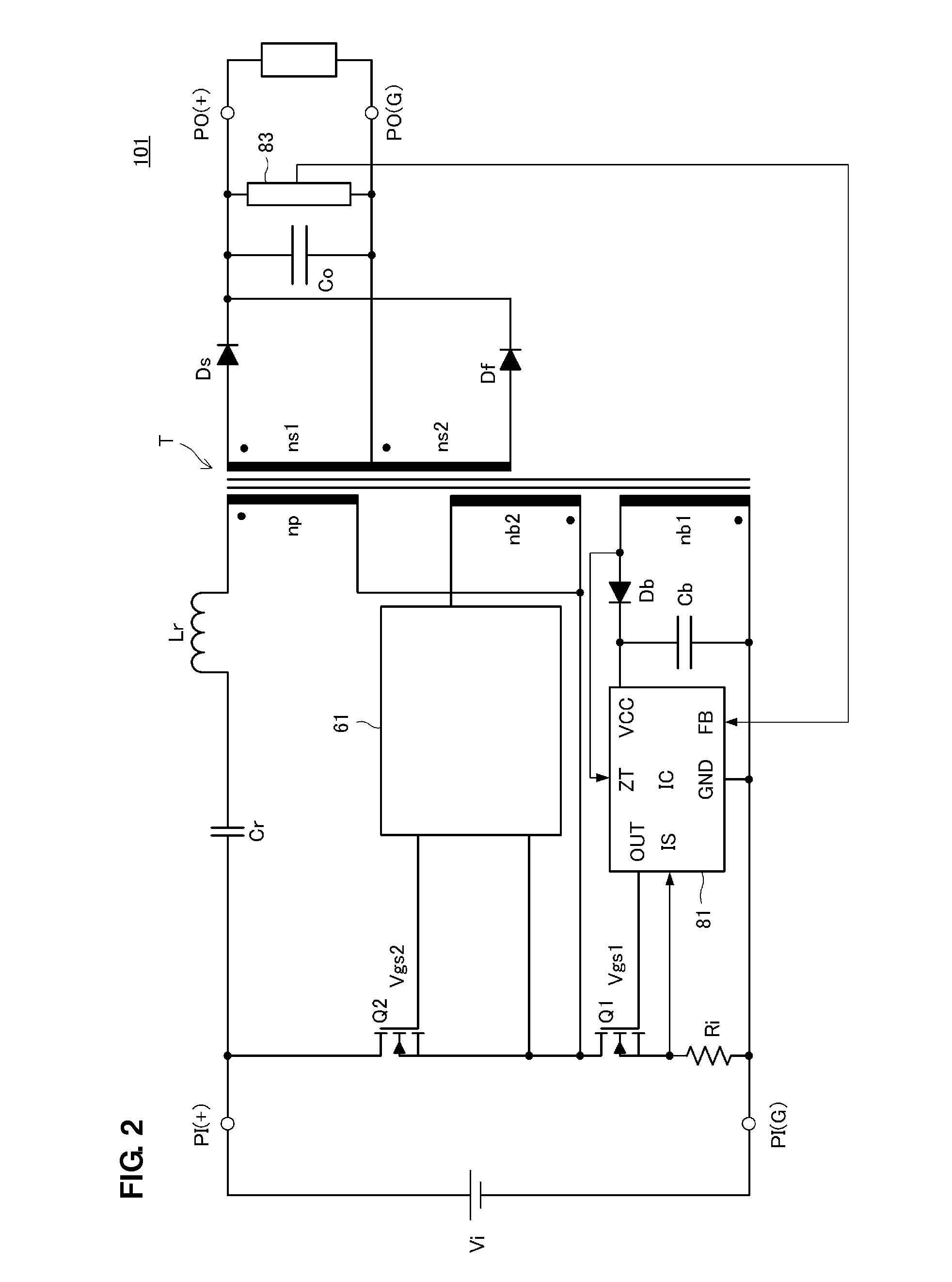
[0071]FIG. 2 is the circuit diagram of a switching power supply apparatus 101 according to the first preferred embodiment. The voltage of a direct-current input power supply Vi is input between the input terminals PI(+) and PI(G) of this switching power supply apparatus 101. In addition, a predetermined direct-current voltage is output to a load Ro connected between the output terminals PO(+) and PO(G) of the switching power supply apparatus 101.

[0072]Between the input terminals PI(+) and PI(G), a first series circuit is provided and includes a first switching element Q1, a second switching element Q2, and a current detection resistor Ri connected in series. The first switching element Q1 and the second switching element Q2 include FETs, the drain terminal of the high-side second switching element Q2 is connected to the input terminal PI(+), and the...

second preferred embodiment

[0098]FIG. 8 is the circuit diagram of a switching power supply apparatus 102 according to a second preferred embodiment.

[0099]While being different from the switching power supply apparatus 101 according to the first preferred embodiment illustrated in FIG. 2, FIG. 8 specifically illustrates the configuration of a switching control IC 84 and the configuration of a second switching control circuit 63.

[0100]A series circuit including a constant current circuit CC1 and a capacitor C3 is connected to the OUT terminal of the switching control IC 84, and connected so that the charging voltage of the capacitor C3 is input to an IS terminal.

[0101]The voltage of a counter electromotive force induced in the first drive winding nb1 due to the turnoff of the second switching element Q2 is input to a ZT terminal, and hence, the switching control IC 84 puts the OUT terminal into a high level. Accordingly, the first switching element Q1 is turned on.

[0102]On the basis of the input voltage of the ...

third preferred embodiment

[0106]FIG. 9 is the circuit diagram of a switching power supply apparatus 103 according to a third preferred embodiment. A second switching control circuit 62 in the switching power supply apparatus 103 is different from FIG. 8. In addition, a circuit on a secondary side is different from the circuits illustrated in FIG. 2 and FIG. 8.

[0107]In the second switching control circuit 62, a constant current circuit preferably includes transistors Q4 and Q5 and resistors R7 and R8. Accordingly, the basic circuit operation of the second switching control circuit 62 is the same as the second switching control circuit 63 illustrated in FIG. 8. In addition, a series circuit including a diode D5 and a resistor R6 is connected in parallel to a resistor R4. Therefore, the rise of the driving voltage Vgs2 of the second switching element Q2 is set due to the parallel impedance of the R4 and the R6, and the fall thereof is dominantly set only due to the impedance of the R4.

[0108]An FET Qs and an FET...


PUM


Abstract

In a switching power supply apparatus, a first switching element is controlled by a driving voltage output from a switching control IC. A second switching control circuit controls the on-time of a second switching element so that the time ratio of the on-time of the second switching element to the on-time of the first switching element becomes almost constant with respect to a change in a load current. In a normal load state, since a square wave output from a frequency setting unit within the switching control IC is output with no change, a converter operates in a current-continuous mode. In a light load state, a driving signal generation unit within the switching control IC is subjected to blanking with the period of a signal output from a maximum frequency setting unit and an oscillation frequency is reduced. Accordingly, the converter operates in a current-discontinuous mode.

Description

BACKGROUND OF THE INVENTION[0001]1. Field of the Invention[0002]The present invention relates to a switching power supply apparatus that maintains high power conversion efficiency under a condition of extensive power supply to a load.[0003]2. Description of the Related Art[0004]In the past, in order to reduce electric power consumption during a standby time of a load circuit serving as a supply destination of a power-supply voltage, i.e., standby power consumption, there has been a switching power supply apparatus causing a converter for a normal time and a converter for a standby time to operate by switching therebetween or a switching power supply apparatus switching between operation modes at a normal time and a standby time in a single converter.[0005]The following three types of switching power supply apparatuses have been used as the switching power supply apparatus switching between the operation modes in the above-mentioned single converter.[0006]The first type is a switchin...

Claims


Application Information

Patent Timeline
Patent Type & Authority Applications(United States)
IPC IPC(8): H02M3/335
CPCH02M3/33507Y02B70/16H02M2001/0032H02M3/3376H02M1/0032Y02B70/10H02M3/33538H02M3/33553
Inventor HOSOTANI, TATSUYA
Owner MURATA MFG CO LTD
Why Eureka
Try Eureka