Positive displacement expander

a technology of expander and expander, which is applied in the direction of machines/engines, domestic cooling devices, lighting and heating devices, etc., can solve the problems of pressure loss, vibration in equipment, and pressure loss, and achieve the effect of reducing equipment effectively in vibration, reducing equipment in reliability and operating efficiency, and reducing the variation of suction fluid pressur

Inactive Publication Date: 2009-07-16
DAIKIN IND LTD
View PDF3 Cites 20 Cited by
  • Summary
  • Abstract
  • Description
  • Claims
  • Application Information

AI Technical Summary

Benefits of technology

[0039]In accordance with the first aspect of the present invention, the pressure snubbing means (70) for inhibiting variation in the pressure of at least either suction fluid or discharge fluid in the expansion mechanism (60) is provided within the casing (31), whereby the pressure snubbing means (70) is allowed to exercise its inhibitive force at the position extremely close to the suction and discharge parts of the expansion mechanism (60) which are sources of pressure variation. Accordingly, the action of inhibition against pressure variation is exhibited more effectively than is possible in the prior art and the property of response of the inhibitive action is expedited. Therefore, variation in the pressure of suction fluid is inhibited more effectively. Accordingly, the equipment is reduced effectively in vibration and pressure loss due to pressure variation and, in addition, it becomes possible to improve the equipment in reliability and operating efficiency.
[0040]Especially, in accordance with the second aspect of the present invention, the pressure snubbing chamber (71) performs suction of refrigerant from and discharge of refrigerant into either the suction passageway (34) or the discharge passageway (35) which is a source of pressure variation, whereby pressure variation is inhibited. As a result of this arrangement, the action of inhibition is worked further effectively and the property of response is improved to a further extent.
[0041]Furthermore, in accordance with the third aspect of the present invention, the pressure snubbing chamber (71) is provided within the forming member (61, 62) such as the rear and front heads of the expansion mechanism (60). As a result of this arrangement, not only inhibitive force can positively be exerted from the position near to either the suction passageway (34) or the discharge passageway (35), but it is also possible to prevent the equipment from growing in size because there is no need to secure a separate installation space in which to form the pressure snubbing chamber (71).
[0042]In addition, in accordance with the fourth aspect of the present invention, the attachment member (83) in which the pressure snubbing chamber (71) is formed is mounted to the expansion mechanism (60) by making utilization of a space within the casing (31). Therefore, pressure pulsation in the expansion mechanism (60) is easily and effectively inhibited, just by additional attachment of the attachment member (83), especially to an existing positive displacement expander.
[0043]In addition, in accordance with the fifth aspect of the present invention, the pressure snubbing chamber (71) is divided by the partitioning member (77) into the inflow / outflow chamber (72) in fluid communication with the suction passageway (34) and the back pressure chamber (73). The partitioning member (77) displaces in response to pressure variation to thereby cause the inflow / outflow chamber (72) to vary in volume. As a result of such arrangement, it becomes possible to positively perform discharge of refrigerant into either the suction passageway (34) or the discharge passageway (35) from the inflow / outflow chamber (72) and suction of refrigerant into the inflow / outflow chamber (72) from either the suction passageway (34) or the discharge passageway (35). By means of this, pressure variation is positively and effectively inhibited.
[0044]Especially, in the fifth aspect of the present invention, the back pressure chamber (73) is brought into fluid communication with the internal space (S) of the casing (31) filled up with the compression mechanism's (50) discharge pressure, whereby the discharge pressure of the compression mechanism (50) can be used as a back pressure. Accordingly, there is no need to provide a separate back pressure means and pressure variation is effectively inhibited by an inexpensive and simple configuration as compared to the case when using an accumulator which is rather expensive and heavily equipped.

Problems solved by technology

Incidentally, the suction flow rate of the positive displacement expander during the suction process and the discharge flow rate of the positive displacement expander during the discharge process are not constant, and refrigerant pressure pulsation (pressure variation) occurs at the inlet and outlet sides and pressure loss is caused due to the pressure pulsation.
In addition, such a pressure pulsation triggers pressure loss and vibration in the equipment.

Method used


Image

  • Positive displacement expander
  • Positive displacement expander
  • Positive displacement expander

Examples


first embodiment

of the Invention

[0065]An air conditioner (10) of the present embodiment is equipped with a positive displacement expander of the present invention.

Overall Structure of the Air Conditioner

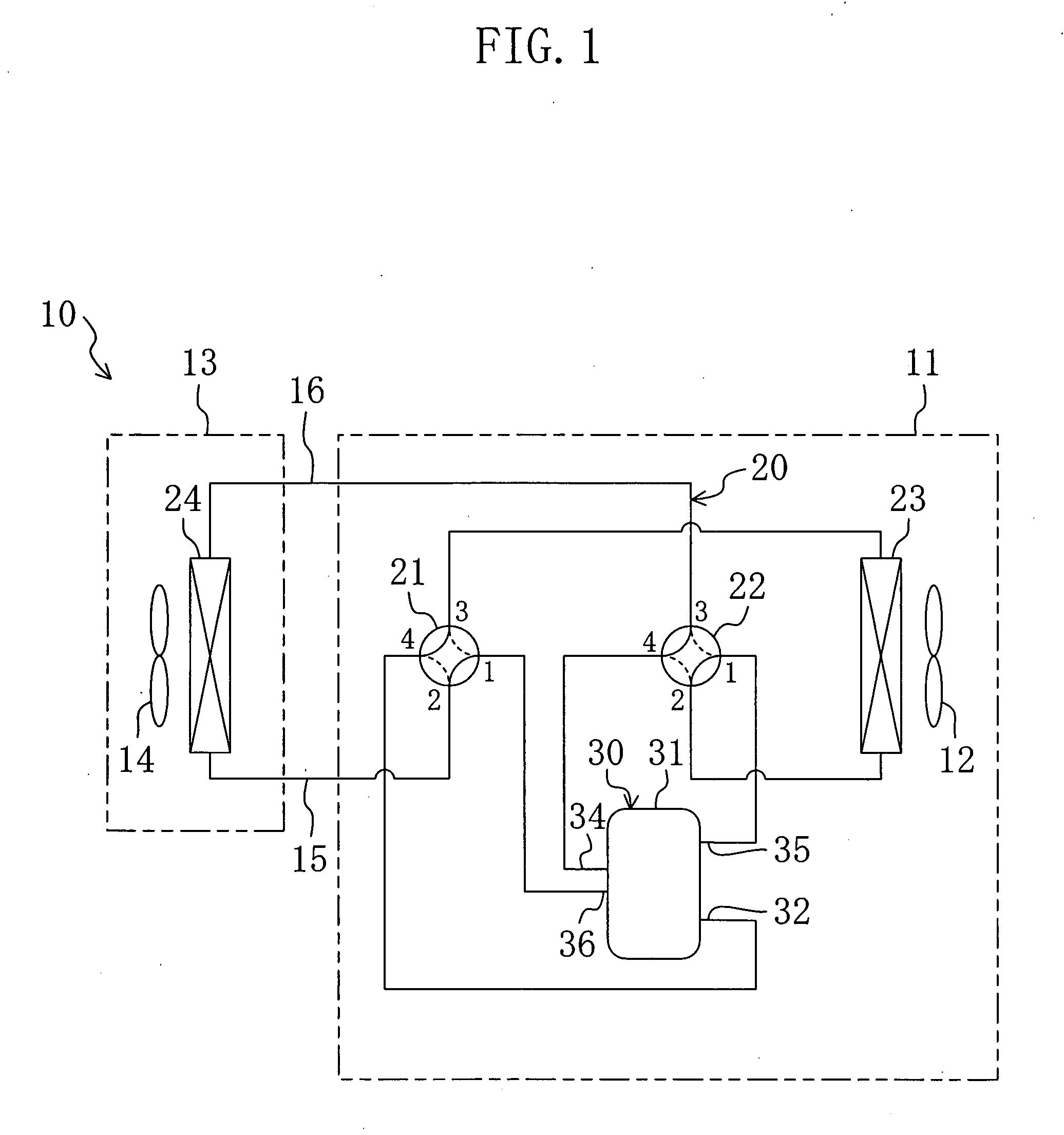
[0066]As shown in FIG. 1, the air conditioner (10) is a so-called “separate type” air conditioner, and is equipped with an outdoor unit (11) and an indoor unit (13). The outdoor unit (11) houses therein an outdoor fan (12), an outdoor heat exchanger (23), a first four-way switch valve (21), a second four-way switch valve (22), and a compression / expansion unit (30). On the other hand, the indoor unit (13) houses therein an indoor fan (14) and an indoor heat exchanger (24). The outdoor unit (11) is installed outside a building. The indoor unit (13) is installed inside the building. In addition, the outdoor unit (11) and the indoor unit (13) are connected together by a pair of interunit lines (15, 16). The compression / expansion unit (30) will later be described in detail.

[0067]The air conditioner (10) ...

second embodiment

of the Invention

[0124]Referring next to FIG. 9, a second embodiment of the present invention will be described below.

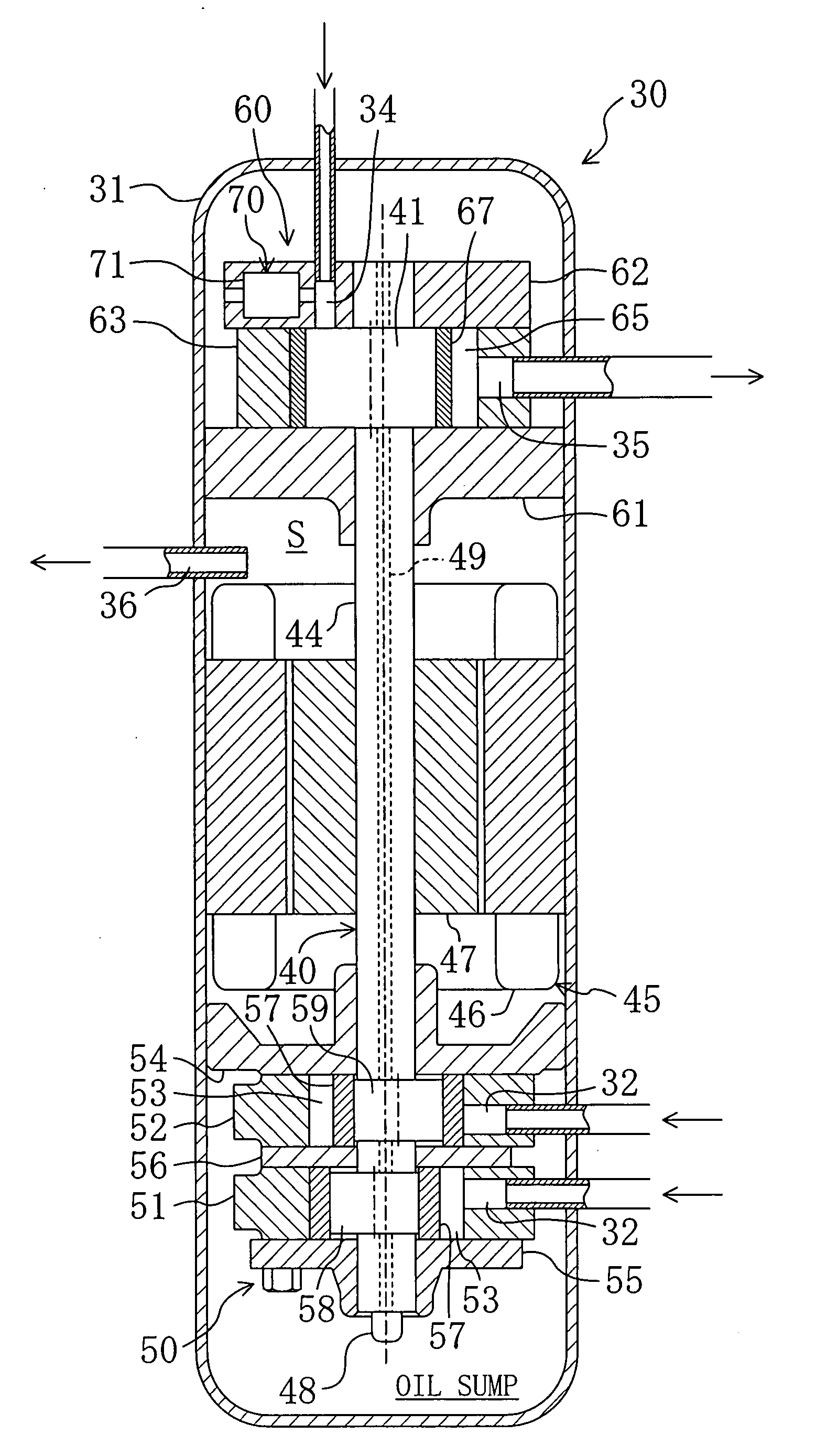
[0125]The second embodiment is a modification of the first embodiment in that the pressure snubbing means (70) is modified in configuration. In other words, unlike the first embodiment that makes utilization of discharge fluid from the compression mechanism (50) as a back pressure of the back pressure chamber (73), suction fluid in the inflow port (34) is utilized as a back pressure in the second embodiment.

[0126]More specifically, the pressure snubbing chamber (71) is provided, between itself and the inflow port (34), with a connecting pipe (81). One end of the connecting pipe (81) is connected upstream of the connecting position of the communicating passageway (74) in the inflow port (34) while the other end thereof is connected to the back pressure chamber (73) of the pressure snubbing chamber (71), and a capillary tube (82) is provided along the connecting pipe (8...

third embodiment

of the Invention

[0133]In the following, a third embodiment of the present invention will be described with reference to FIG. 11.

[0134]Instead of the arrangement of the first embodiment in which the pressure snubbing chamber (71) is formed within the rear head (62), the pressure snubbing chamber (71) of the third embodiment is formed in an attachment member (83) which is supported by the rear head (62).

[0135]The attachment member (83) is shaped like a plate which is slightly smaller in size than the rear head (62). Being approximately centered on the inflow port (34), the attachment member (83) is mounted onto the upper end surface of the rear head (62). The inflow port (34) is formed such that it is vertically extended through the attachment member (83) and the rear head (62). And, the pressure snubbing chamber (71) is formed within the attachment member (83) in the same manner that it is formed in the rear head (62) in the first embodiment.

[0136]In this case, it is possible to moun...


PUM


Abstract

A casing (31) houses therein an expansion mechanism (60) and a compression mechanism (50). The expansion mechanism (60) has a rear head (62) in which a pressure snubbing chamber (71) is provided. The pressure snubbing chamber (71) is divided by a piston (77) into an inflow/outflow chamber (72) which fluidly communicates with an inflow port (34) and a back pressure chamber (73) which fluidly communicates with the inside of the casing (31). The piston (77) is displaced in response to suction pressure variation whereby the volume of the inflow/outflow chamber (72) varies. This enables the inflow/outflow chamber (72) to directly perform supply of refrigerant to or suction of refrigerant from the inflow port (34) which is a source of pressure variation, thereby making it possible to effectively inhibit suction pressure variation.

Description

TECHNICAL FIELD[0001]The present invention relates to a positive displacement expander, and concerns in particular measures for pressure pulsation reduction.BACKGROUND ART[0002]A positive displacement expander of the type which generates power by the expansion of high pressure fluid is known in the conventional technology (see, for example, JP-A-2004-190938). This type of positive displacement expander is employed, for example, in a refrigeration apparatus configured to perform a vapor compression refrigeration cycle.[0003]Such a refrigeration apparatus includes a refrigerant circuit in which a compressor, a cooler, a positive displacement expander, and an evaporator are connected by piping, and the refrigerant circuit performs a vapor compression refrigeration cycle. In the positive displacement expander, sucked-in high pressure refrigerant is discharged after expansion and the resulting internal energy is converted into power for rotating the compressor.[0004]Incidentally, the suc...

Claims


Application Information

Patent Timeline
Patent Type & Authority Applications(United States)
IPC IPC(8): F25D9/00
CPCF01C1/322F01C21/006F01C11/002F01C1/356F01C13/04F01C21/18
Inventor KUMAKURA, EIJIOKAMOTO, MASAKAZUOKAMOTO, TETSUYASAKITANI, KATSUMI
Owner DAIKIN IND LTD
Why Eureka
Try Eureka