Supercharge Your Innovation With Domain-Expert AI Agents!

Pulsation combustion heating furnace

A technology of pulsating combustion and heating furnace, which is applied in the direction of pulsating combustion, combustion chamber, combustion method, etc. It can solve the problems of affecting the stability of the burner, the failure of the burner to start vibration, and the difficulty of large-scale pulsating burner, etc.

Inactive Publication Date: 2011-09-21
HARBIN INST OF TECH
View PDF7 Cites 3 Cited by
  • Summary
  • Abstract
  • Description
  • Claims
  • Application Information

AI Technical Summary

Problems solved by technology

[0003] The coupling between the pulsation burner system is very strong, and any slight change in any component will lead to unstable operation of the burner, or even failure to form pulsation combustion
In the currently applied pulsating combustion furnace, the supply of fuel and air is usually controlled by mechanical valves, and the pressure pulsation of the pulsating burner will cause the vibration of various components, so the existence of the mechanical valve will affect the stability of the overall operation of the burner
Whether the pulsating burner can form stable pulsating combustion depends on the acoustic structure. The increase in the heating surface of the tailpipe will cause the burner to fail to vibrate, making it difficult to enlarge the pulsating burner

Method used


Image

  • Pulsation combustion heating furnace
  • Pulsation combustion heating furnace
  • Pulsation combustion heating furnace

Examples


Embodiment Construction

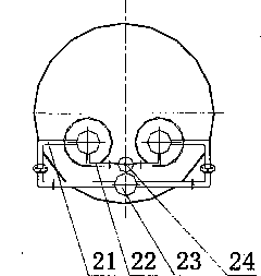
[0007] Such as figure 1 , figure 2 As shown, the above-mentioned pulsating combustion heating furnace is composed of an air inlet 1, a gas inlet 2, an air supply chamber 23, an air pipeline 21, a gas supply chamber 24, a gas pipeline 22, a mixing chamber 3, an ignition device 4, Combustion chamber 5, bent tail pipe 6, decoupling chamber 18, furnace body 20, liquid inlet and outlet pipe 7, smoke pipe 12, flue 10, blower fan 11 form. Among them, the pulsating burner composed of mixing chamber 3, ignition device 4, combustion chamber 5 and curved tailpipe 6 is arranged side by side in two or more sets in the furnace and has the same geometric structure. Two or more sets of pulsating burners share the air supply chamber 23, the gas supply chamber 24 and the decoupling chamber 18, and all smoke pipes are drawn from the decoupling chamber 18.

[0008] Such as figure 1 , figure 2 As shown, the diameters (areas) of the fuel gas supply chamber 24, the gas pipeline 22, the air sup...


PUM


Abstract

The invention discloses a pulsation combustion heating furnace. Two sets of or more than two sets of intermittent combustors with the same geometric shape are arranged in parallel; the combustors share a fuel gas supply chamber, an air supply chamber and a decoupling chamber; and all smoke pipes are led out of the decoupling chamber. Fuel gas and air are continuously and stably supplied, and the air inlet pipeline is not provided with any valve. The supply pipelines of the fuel gas and the air are arranged mutually vertically, and the diameters (areas) of the fuel gas / air supply chamber and the fuel gas / air pipeline are determined by the chemical equivalent ratio and the flow of the fuel gas / air. A bent tail pipe is provided with a main heated surface of the pulsation combustion heating furnace, and the smoke pipes are provided with accessory heated surfaces. When the pulsation combustion heating furnace runs stably, the pressure pulsation in the decoupling chamber, the air supply chamber and the fuel gas supply chamber forms phase difference of half period, and the running noise can be reduced.

Description

technical field [0001] The invention relates to a pulse combustion heating furnace Background technique [0002] The pulsating burner is a periodic combustion process under the control of certain acoustic conditions. The difference from the conventional steady-state combustion is that the parameters such as pressure, temperature, and speed in the pulsating burner change periodically with time, which is a special non-smooth combustion process. Stabilizes the combustion process. The pulsation burner is widely used due to its advantages of high combustion efficiency, high combustion intensity and low pollutant emission. [0003] The coupling between the pulsating burner systems is very strong, and any slight change in any component will lead to unstable operation of the burner, or even failure to form pulsating combustion. In the currently used pulsating combustion furnaces, the supply of fuel and air is usually controlled by mechanical valves. The pressure pulsation of the p...

Claims


Application Information

Patent Timeline
IPC IPC(8): F23C15/00F24H9/18
Inventor 徐艳英董芃翟明朱群益
Owner HARBIN INST OF TECH
Features
  • R&D
  • Intellectual Property
  • Life Sciences
  • Materials
  • Tech Scout
  • Unparalleled Data Quality
  • Higher Quality Content
  • 60% Fewer Hallucinations
Learn More