Lens driver, imaging device, lens barrel used in the imaging device, and camera body

A technology of lens driving device and lens barrel, which is applied in the directions of installation, optics, and instruments, and can solve the problems of inability to realize the miniaturization of the camera device, errors, etc.

Inactive Publication Date: 2007-01-03
PANASONIC CORP
View PDF5 Cites 39 Cited by
  • Summary
  • Abstract
  • Description
  • Claims
  • Application Information

AI Technical Summary

Problems solved by technology

[0034] In addition, in the focus adjustment device for a video camera described in Patent Document 4, in order to detect the origin position of the stepping motor, a structure such as a photoelectric sensor is required separately, and there is a problem that the miniaturization of the imaging device cannot be achieved.
[0035] In addition, the lens drive device described in Patent Document 5 detects the origin position by moving the driven body to a mechanically limited limit position. An error occurs when the amount of movement from the origin

Method used


Image

  • Lens driver, imaging device, lens barrel used in the imaging device, and camera body
  • Lens driver, imaging device, lens barrel used in the imaging device, and camera body
  • Lens driver, imaging device, lens barrel used in the imaging device, and camera body

Examples


no. 1 approach

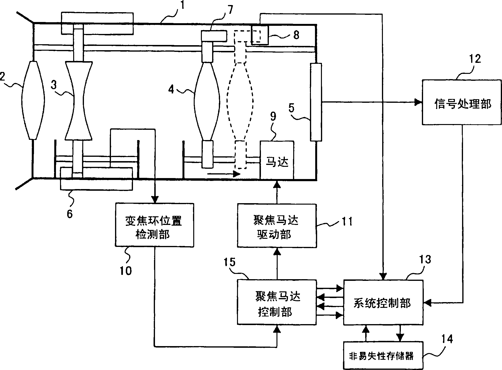
[0179] figure 1 It is a schematic diagram and a block diagram of a lens driving device according to a first embodiment of the present invention. figure 1 Among them, 1 is a lens barrel, 2 is a fixed lens fixed on the lens barrel 1, and 3 is a zoom lens, and the zoom lens 3 rotates the zoom ring 6 along the outer circumference of the lens barrel 1, and the optical axis direction A lens that moves the zoom lens to adjust the zoom magnification. The focus lens 4 is a lens for adjusting focus by moving in the direction of the optical axis along a threaded lead screw by rotation of a motor 9 as a driving mechanism.

[0180] Motor 9 is a stepping motor, in figure 1 In an example, the rotation is performed according to the phase of the motor coil drive signal (excitation signal) output from the focus motor drive unit 11 . Reference numeral 5 denotes an imaging element as an imaging device, which converts an image of an object captured after passing through the fixed lens 2, the...

no. 2 approach

[0223] Next, a second embodiment of the present invention will be described. described in the first embodiment figure 1 , figure 2 The structure shown, and the image 3 , 4 The origin detection operation at the time of the described process adjustment is also the same in the second embodiment.

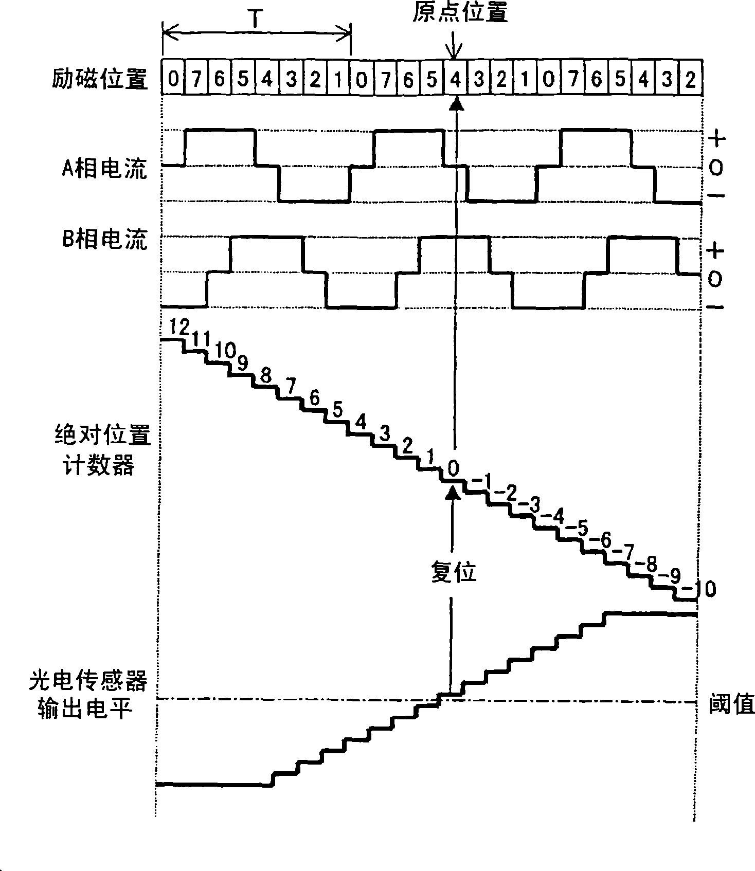
[0224] refer to Figure 8 , 9 , the origin detection operation of the focus lens 4 in normal use in the second embodiment will be described. Figure 8 It is an explanatory diagram of the origin detection operation in normal use according to the second embodiment. also, Figure 8 The excitation position, A-phase current, B-phase current, absolute position counter and photoelectric sensor output level indicated by image 3 The description is the same as in , so the description of the overlapping part is omitted.

[0225] In the second embodiment, unlike the first embodiment, the excitation position is decremented by two as the focus lens 4 moves toward the imaging element 5 si...

no. 3 approach

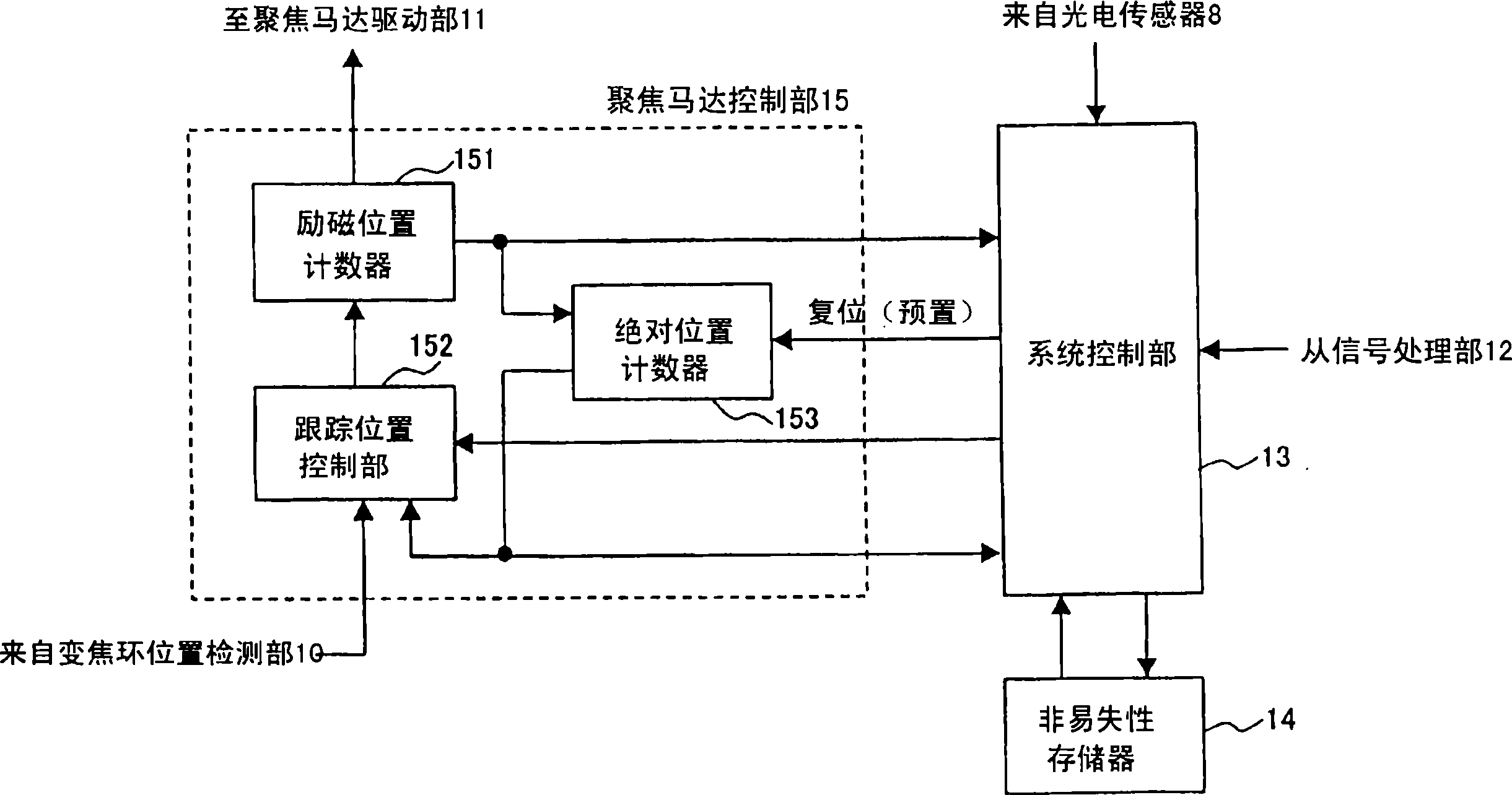
[0236] Next, a third embodiment of the present invention will be described. For the same as described in the first embodiment figure 1 , figure 2The structure shown is repeated, and the explanation is omitted. In the third embodiment, an example in which the focus motor drive unit 11 rotationally drives the drive motor 9 by approximately sinusoidal drive (also referred to as micro-step drive) will be described. also, figure 2 The excitation position counter 151 in is a 5-bit counter that expresses one cycle (360 degrees) of the driving electrical angle of the motor 9 with a count value of 32, and the absolute position counter 153 operates synchronously with the count value of the excitation position counter 151, as specified later. Conditions are preset or reset.

[0237] Below, refer to Figure 10 Explain its action. Figure 10 It is an explanatory diagram of the origin detection operation at the time of process adjustment in the third embodiment. Figure 10 The ind...


PUM


Abstract

Lens position calculating means (13) is provided for determining the phase of a drive signal of driving means (9) as a reference position of the taking lens when the output value of a position detection sensor (8) reaches a threshold. The lens position calculating means (13) determines the position by addition / subtraction to / from the reference position read out of reference position storage means (14) as a judgment position, detects the output value of the position detection sensor (8) at the judgment position at the timing synchronous with the drive signal, judges the output value of the position detection sensor (8) at the judgment position, and again determines the reference position.

Description

technical field [0001] The present invention relates to imaging devices such as still cameras and video cameras, lens driving devices for controlling the position of their lenses, lens barrels for imaging devices, and camera bodies. Background technique [0002] Conventionally, a method has been proposed in which the lens unit is driven by a motor using a shielding member and a photosensor mounted on the lens unit, and the output level of the photosensor is monitored when the shielding member sweeps across the photosensor, and the output level of the lens unit is detected. origin position (for example, refer to Patent Document 1). [0003] use Figure 58 A conventional lens driving device will be described. Figure 58 It is a schematic diagram and a block diagram of an example of a conventional lens driving device. The captured image of the subject transmitted through the fixed lens 72 fixed to the lens barrel 71 , the zoom lens 73 , and the focus lens 74 is converted into ...

Claims


Application Information

Patent Timeline
Patent Type & Authority Applications(China)
IPC IPC(8): G02B7/08
Inventor 本庄谦一渋野刚治林孝行阪本圭司桑原巧河原博之本庄弘典弓木直人村山正人
Owner PANASONIC CORP
Why Eureka
Try Eureka