
Optical integrator

An optical integrator, uniform distribution technology, applied in the field of optical integrator

Inactive Publication Date: 2007-01-10
KONINKLIJKE PHILIPS ELECTRONICS NV
View PDF0 Cites 1 Cited by
  • Summary
  • Abstract
  • Description
  • Claims
  • Application Information

AI Technical Summary

Problems solved by technology

Any such solution must be fabricated and assembled into an LCD device to be a simple

Method used


Image

  • Optical integrator
  • Optical integrator
  • Optical integrator

Examples


Embodiment Construction

[0049] Figure 5 An optical integrator plate 17 according to the invention is shown schematically. The optical integrator plate 17 basically comprises a transparent polymer sheet 19 in which elongate particles 21 are suspended. The elongated particles 21 are homogeneously distributed in the aggregate and their longitudinal axes are aligned perpendicular to the surface 23 of the (thin) flake. However, the elongated particles 21 are free to rotate about their longitudinal axis. From Figure 5 As can be seen in , the particles 21 are rotated to different angles and are randomly arranged in this regard.

[0050] Figure 6 A microscopic image of an optical integrator plate 17 according to the invention is shown. From Figure 6 In , it can be seen that the elongated particles (dark regions) are evenly distributed throughout the aggregate (light regions).

[0051] Now, the method of manufacturing the optical integrator plate 17 according to the present invention will be descri...


PUM

PropertyMeasurementUnit
thicknessaaaaaaaaaa
thicknessaaaaaaaaaa
lengthaaaaaaaaaa

Abstract

A method of manufacturing an optical integrator panel is provided. The method comprises the steps of: suspending a plurality of elongate particles in a liquid; applying an electric or magnetic field to the suspension to orientate the particles with parallel longitudinal axes; and solidifying the liquid to fix the orientation of the particles, thereby forming an optical integrator panel having a homogeneous distribution of elongate particles. An optical integrator panel is also provided. The optical integrator panel is adapted to reduce the angular dependence of contrast of a liquid crystal display. Specifically, the optical integrator panel is for placement in the path of reflected or transmitted light emitted by the liquid crystal display. The optical integrator panel comprises: a solid transparent panel; and a plurality of elongate particles homogeneously distributed in the panel, wherein the plurality of elongate particles are orientated with parallel longitudinal axes.

Description

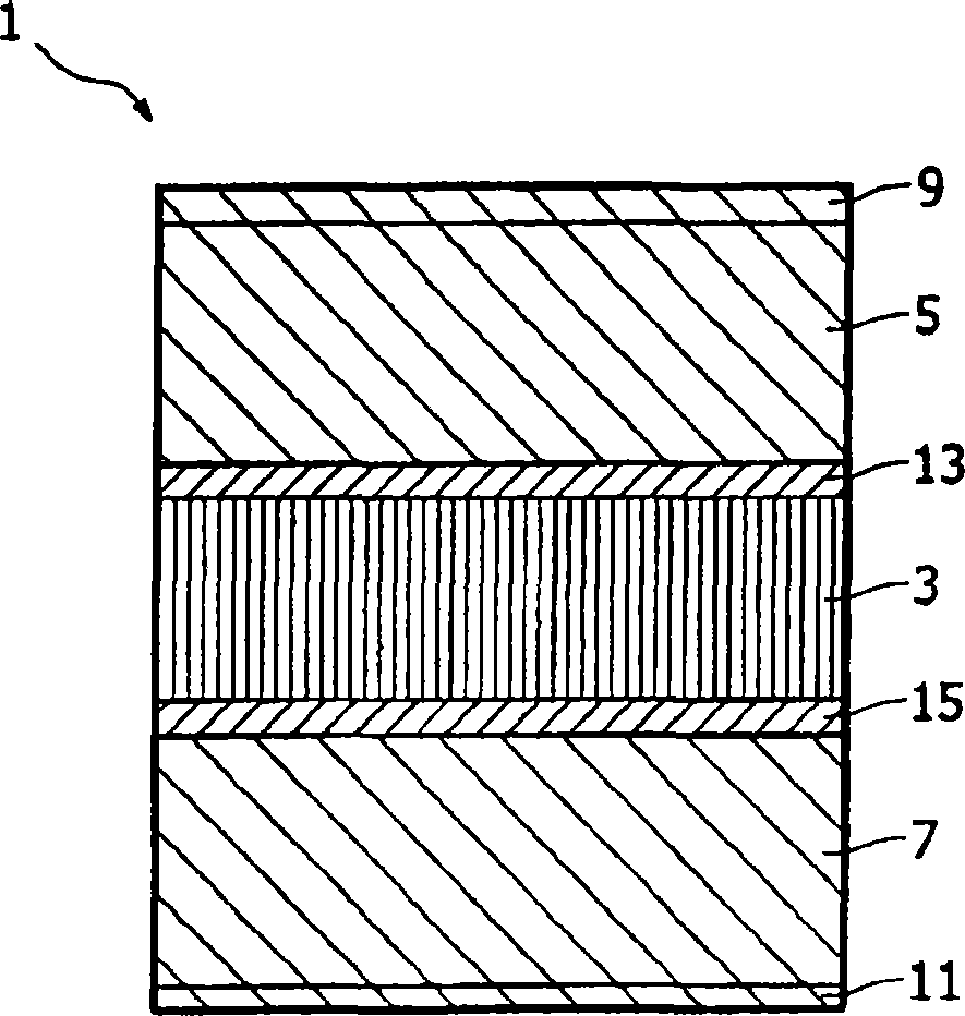
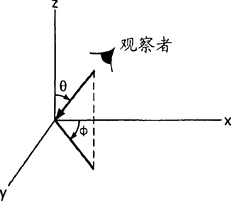
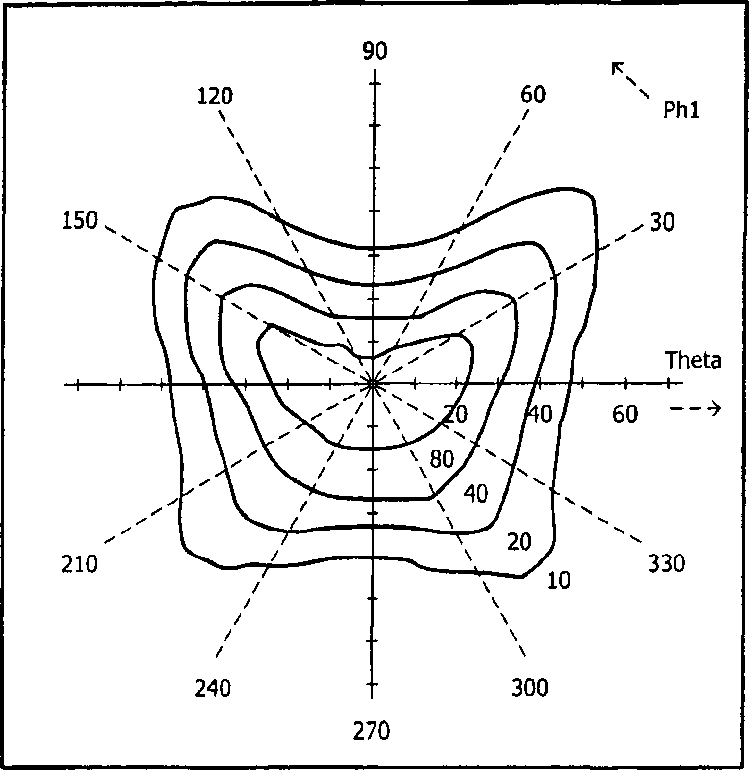
technical field [0001] The present invention relates to optical integrators. More particularly, but not exclusively, the present invention relates to optical integrators for reducing the viewing angle dependence (dependence) of image contrast of liquid crystal display (LCD) devices. The invention also relates to an LCD device comprising an optical integrator. Background technique [0002] LCD devices are common in many types of electronic equipment, such as visual display units (VDUs) for computers and televisions. These devices are used to generate and communicate information in the form of visual images to a user or viewer. One of the requirements of such devices is that the generated images should be viewable from a wide range of viewing angles. Another requirement is that the features of the generated image should not vary with viewing angle. [0003] One of the most common forms of LCD devices is the twisted nematic (TN) configuration. figure 1 An exemplary TN cell...

Claims


Application Information

Patent Timeline
Patent Type & Authority Applications(China)
IPC IPC(8): G02B5/02G02F1/1335
CPCG02B5/0236G02F1/133504G02B5/0278G02F1/1335G02B5/02G02F1/1337
Inventor R·A·M·希克梅特T·范博梅尔
Owner KONINKLIJKE PHILIPS ELECTRONICS NV
Learn More