
Vswr measurement device

A technology of voltage standing wave ratio and measuring equipment, which is applied in the direction of measuring devices, measuring electrical variables, measuring resistance/reactance/impedance, etc., can solve problems such as distortion, and achieve the effect of simplifying the installation process

Inactive Publication Date: 2007-01-17
EVOLIUM
View PDF0 Cites 4 Cited by
  • Summary
  • Abstract
  • Description
  • Claims
  • Application Information

AI Technical Summary

Problems solved by technology

A change in the number of user equipments to be served by the base station will therefore change the VSWR ratio and thus cause distortion of the VSWR measurement

Method used


Image

  • Vswr measurement device
  • Vswr measurement device

Examples


Embodiment Construction

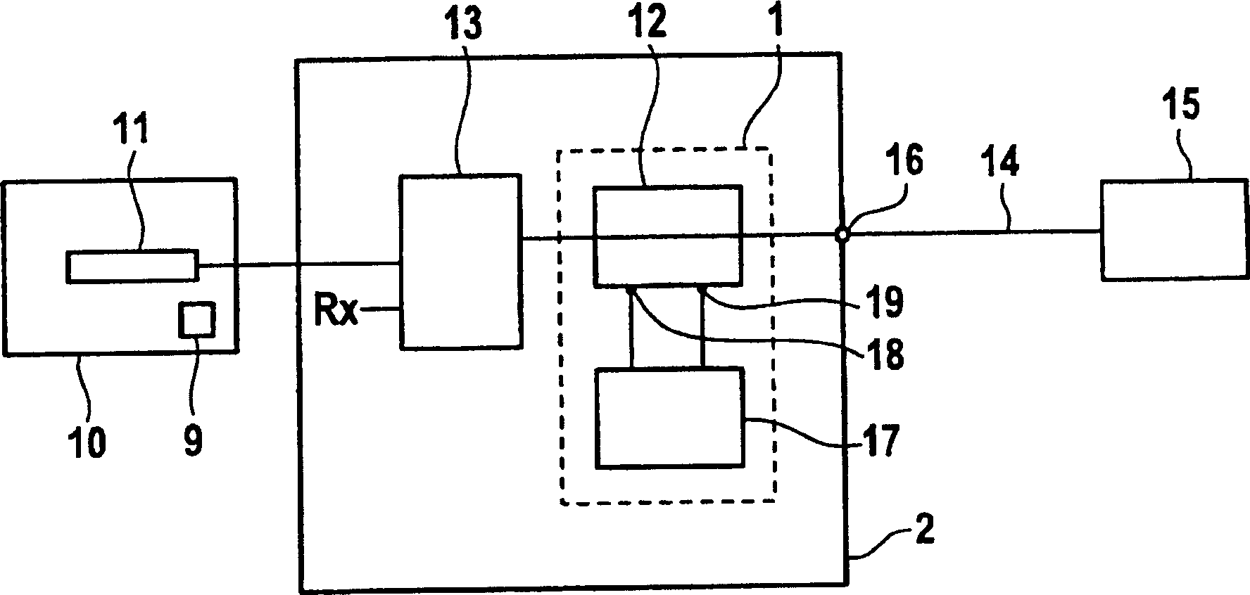
[0022] figure 1 A block diagram of a base station 10 with a VSWR measurement device 1 is shown. The base station 10 has a power generation unit (not shown) for generating radio frequency (RF) CDMA signals. The RF signal is coupled into the antenna network 2 via a transmit chain 11 .

[0023] The antenna network 2 couples the CDMA signal into a duplexer 13 connected to the VSWR measuring device 1 . For clarity, the Rx path is not shown. The input / output port 16 of the VSWR antenna network 2 is connected to the antenna 15 through the feeder line 14 .

[0024] The VSWR measurement device 1 comprises a conventional directional coupler 12 and a measurement unit 17 . The purpose of the directional coupler 12 includes providing an input signal to a measurement unit 17 . The directional coupler 12 outputs a forward signal on port 18 and a reverse signal on port 19 .

[0025] The input signal of the measurement unit 17 comprises a plurality of UE signals, the number of which may ...


PUM


Abstract

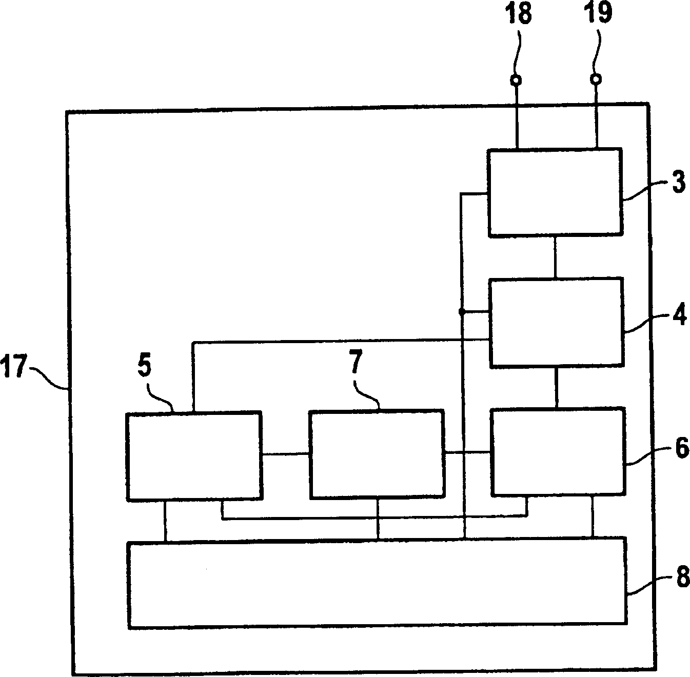
The invention relates to a VSWR measurement device 1 for OFDM signal, in particular CDMA signals, comprising a radio frequency switch 3, a unit 4 for converting the signal from the RF switch into the digital baseband, means 6 for extracting a pilot signal out of a multitude of / OFDM / CDMA signals, a timing unit 5 and a code generator 7 associated with said extraction means, a controller 8.

Description

technical field [0001] The present invention relates to wireless communication networks employing Orthogonal Frequency Division Multiplexing (OFDM) and in particular Code Division Multiple Access (CDMA). More particularly, the invention relates to a VSWR (Voltage Standing Wave Ratio) measuring device for antenna networks that can be integrated into base stations for such communication networks employing OFDM and in particular employing CDMA. Background technique [0002] Operators of wireless communication systems such as UMTS (Universal Mobile Telecommunications System) typically have to manage thousands of base stations. The maximum degree of automated monitoring must be achieved in order to be able to operate the network with good quality at a reasonable cost. [0003] Different methods are used to monitor the antenna and its connecting cables / feeders. One of the most important methods is VSWR monitoring. Using this method, which is basically known to those of ordinary...

Claims


Application Information

Patent Timeline
Patent Type & Authority Applications(China)
IPC IPC(8): G01R27/06H04B17/00
CPCH04B17/0057H04W52/325H04B17/318
Inventor 阿尔夫·诺伊施塔特克尔德·朗格
Owner EVOLIUM
Learn More