Tensioner
A tensioner, compact technology, applied in the direction of belt/chain/gear, mechanical equipment, transmission, etc., can solve problems such as floating, tilting of transmission shaft, and inability to ensure stable movement
- Summary
- Abstract
- Description
- Claims
- Application Information
AI Technical Summary
Problems solved by technology
Method used
Image

Examples
Embodiment 1
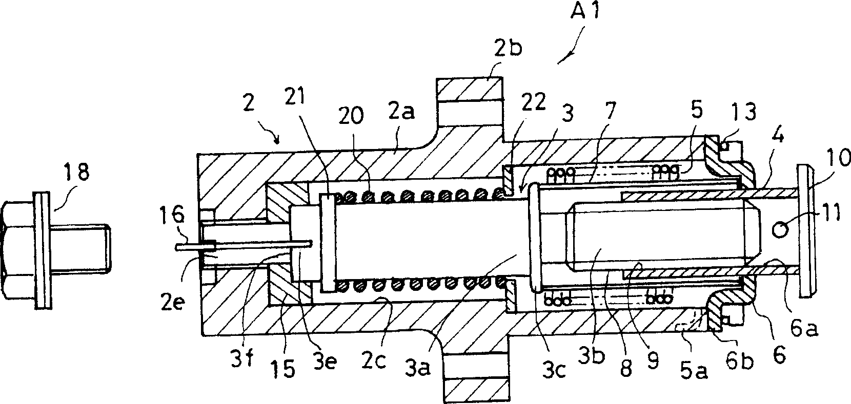
[0049] figure 1 A tensioner A1 according to Embodiment 1 of the present invention is shown. The tensioner A1 includes a housing 2 , a first shaft member 3 , a second shaft member 4 , a torsion spring 5 , a guide 6 and a partition 7 .
[0050] The housing 2 has a cylindrical portion 2 a and a flange portion 2 b extending in a substantially orthogonal direction from the cylindrical portion 2 a. In addition, an accommodation hole 2c is formed extending in the axial direction (the pushing direction) from the cylindrical portion 2a to the flange portion 2b. The front end portion of the storage hole 2c is open, and an assembly of the first and second shaft members 3 and 4, the torsion spring 5, and the partition plate 7 is accommodated in the storage hole 2c.
[0051] The flange portion 2b is used for attachment to an engine body as a device used, and is formed with an attachment hole 2d through which a bolt (not shown) screwed to the engine body passes. When installing to the en...
Embodiment 2
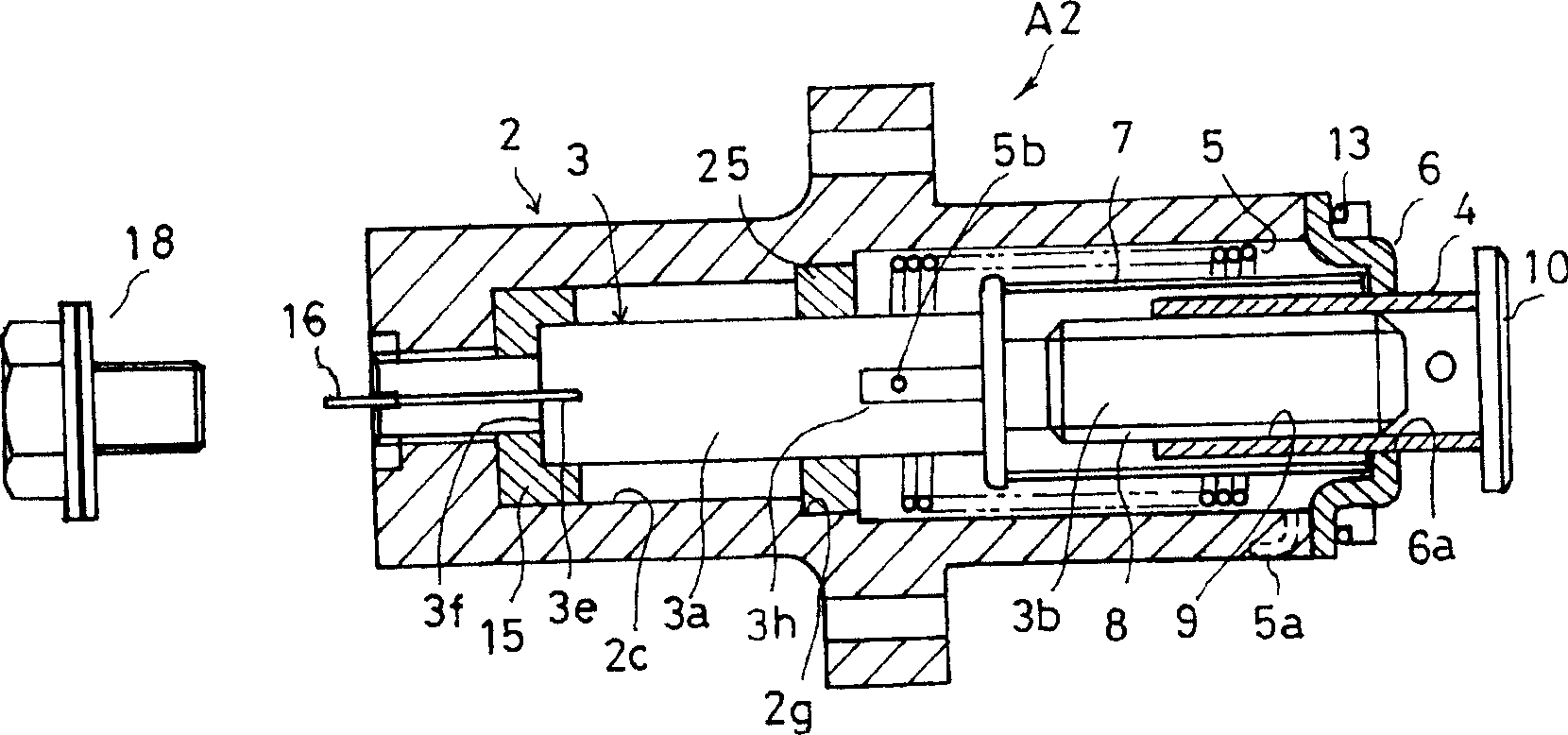
[0065] figure 2 The tensioner A2 of the second embodiment of the present invention is shown. In this embodiment, on the basis of the support seat 15 as a support component, an annular guide 25 as another support component is also provided.
[0066] A press-fit stepped portion 2g is formed on the inner surface of the housing 2 facing the shaft portion 3a of the first shaft member 3, and the annular guide 25 is fixed in the housing 2 by press-fitting the press-fit stepped portion 2g. Such an annular guide 25 serves to rotatably support the outer peripheral surface of the shaft portion 3a.
[0067] An engaging notch 3h extending in the axial direction is formed in the shaft portion 3a of the first shaft member 3, and the hook portion 5b on the other side of the torsion spring 5 is inserted into the hook groove 3f and engaged.
[0068] In this structure, the shaft portion 3a is supported by the support seat 15 on the side of the shaft end portion 3f, and the middle portion is s...
Embodiment 3
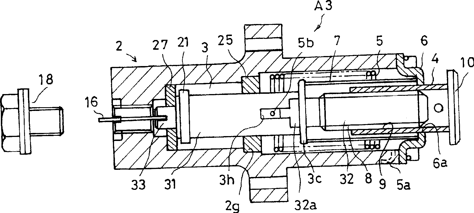
[0070] Figure 3 ~ Figure 5 It shows the tensioner A3 of the third embodiment of the present invention.
[0071] In this embodiment, the first shaft member 3 has a structure divided into two parts of a shaft portion 31 and a threaded shaft portion 32 . The shaft portion 31 is located on the base end side, the threaded shaft portion 32 is located on the distal side (the second shaft member 4 side), and the second shaft member 4 has an external thread portion 8 for screwing on its outer peripheral surface.
[0072] The shaft portion 31 and the threaded shaft portion 32 adopt a structure in which opposite end surfaces engage with each other. That is, if Figure 6 and Figure 7 As shown, a flange portion 3c that abuts against the partition plate 7 is formed on the proximal end surface of the threaded shaft portion 32, and a fitting protrusion 32a with a circular cross section protrudes from the flange portion 3c, and a card with a rectangular cross section The fitting protrusi...
PUM
 Abstract
Description
Claims
Application Information
 - R&D
- Intellectual Property
- Life Sciences
- Materials
- Tech Scout
- Unparalleled Data Quality
- Higher Quality Content
- 60% Fewer Hallucinations
Browse by: Latest US Patents, China's latest patents, Technical Efficacy Thesaurus, Application Domain, Technology Topic, Popular Technical Reports.
© 2025 PatSnap. All rights reserved.Legal|Privacy policy|Modern Slavery Act Transparency Statement|Sitemap|About US| Contact US: help@patsnap.com