

Changeable slide sheet circular centre type internal combustion engine
A technology of internal combustion engines and sliding vanes, applied in the field of fluid machinery, can solve problems such as unsatisfactory load-bearing methods of power transmission mechanisms, achieve the effects of reducing parts, improving work efficiency, and improving sealing performance
- Summary
- Abstract
- Description
- Claims
- Application Information
AI Technical Summary
Problems solved by technology
Method used
Image

Examples
Embodiment Construction
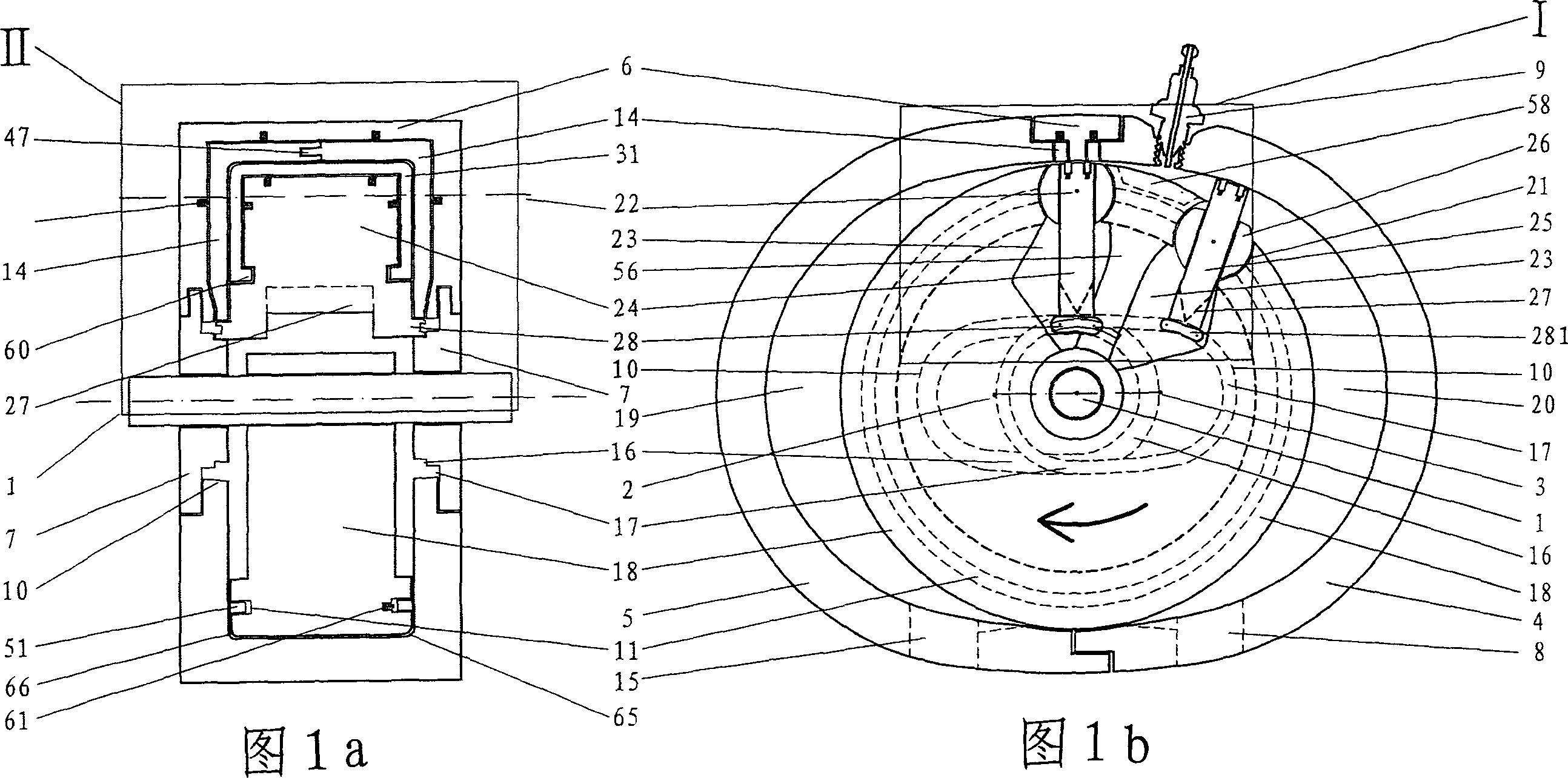
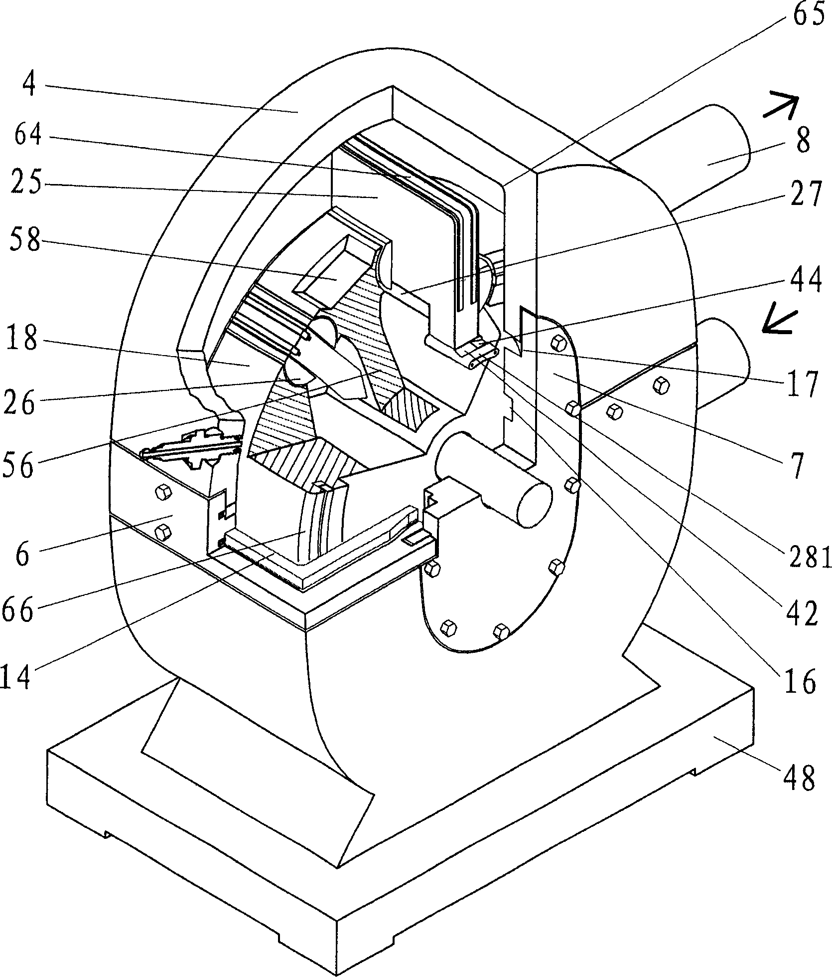
[0028] Figures 1a and b illustrate the structural schematic diagram of a set of slides, image 3 It is a schematic diagram of the structural principle. The cylinder block of the internal combustion engine comprises a lower cylinder block 5, an upper cylinder block 4, and a U-shaped connection cylinder block 6, and cylinder end covers 7 are arranged on both side faces of the cylinder block to form an internal combustion engine casing. The inner walls of the lower cylinder block 5, the upper cylinder block 4 and the connecting cylinder block 6 are connected by multi-section arc surfaces to form a hollow inner cavity. Air inlet 15, the circular arc corner 65 of both sides, the outer edge arc surface 10 of end face guide chute are arranged on the lower cylinder block 5 (see Figure 9 ), base 48, mounting screw hole 50; there are exhaust port 8, spark plug (or fuel injector) 9, the circular arc corner 65 of both sides, the outer edge arc surface 10 of end face guide chute on upper ...
PUM
 Abstract
Description
Claims
Application Information