

Brake device for elevator
A technology of braking device and driving device, which is applied in hoisting devices, brake types, elevators in buildings, etc., and can solve problems such as large installation space of brakes for elevators, large damage to main ropes, and shortened service life of main ropes, etc. question
- Summary
- Abstract
- Description
- Claims
- Application Information
AI Technical Summary
Problems solved by technology
Method used
Image

Examples
Embodiment approach 1
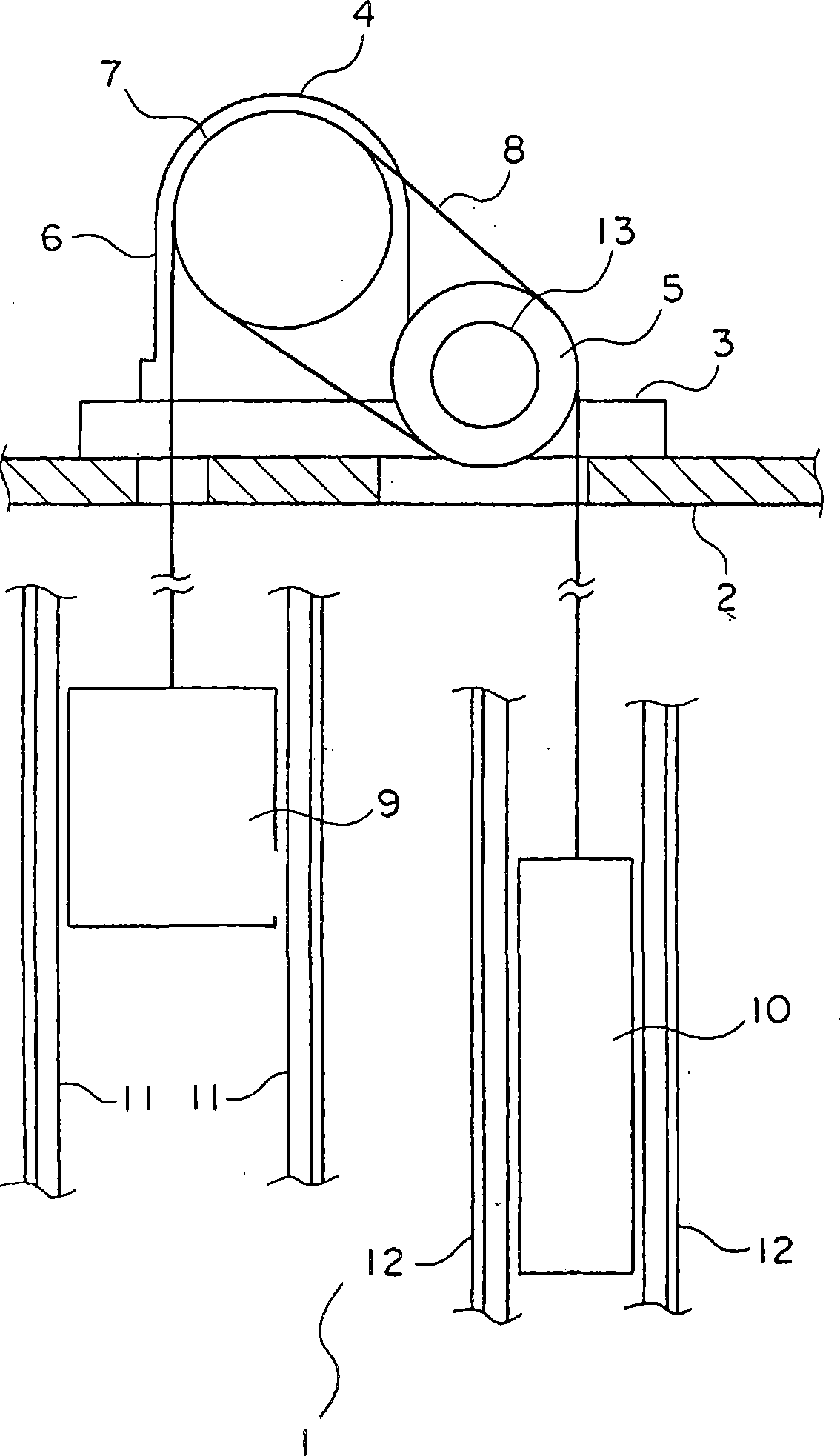
[0014] figure 1 It is a longitudinal sectional view showing the elevator according to Embodiment 1 of the present invention. In the figure, a horizontal beam 2 extending horizontally is arranged on the upper part of the hoistway 1 . On the horizontal beam 2, a pair of traction stands 3 are fixed, and the pair of traction stands 3 are support stands arranged in parallel to each other. A traction machine 4 serving as a driving device and a deflector pulley 5 that is a sheave arranged at a distance from the traction machine 4 are supported on the traction machine stand 3 .
[0015] The hoisting machine 4 has: a drive device body 6 including a motor; and a drive sheave 7 rotated by the drive device body 6 . A plurality of main ropes 8 are wound around the drive sheave 7 and the deflection sheave 5 .
[0016] A car 9 and a counterweight 10 are suspended from the main rope 8 . Each main rope 8 is wound on the driving sheave 7 and the deflecting sheave 5 in order from the car 9 ,...
PUM
 Abstract
Description
Claims
Application Information