Electronic rectifier for exception protection of discharging lamp and discharging lamp

An electronic ballast and abnormal protection technology, which is applied in the direction of electric light sources, electrical components, lighting devices, etc., can solve problems such as abnormal voltage or high current, ineffective protection of circuits, and increased cost, so as to prolong life, Realize the effect of long life and wide adjustment range

Inactive Publication Date: 2008-04-23
PANASONIC CORP
View PDF1 Cites 11 Cited by
  • Summary
  • Abstract
  • Description
  • Claims
  • Application Information

AI Technical Summary

Problems solved by technology

However, sometimes even if the lamp tube is abnormal, the abnormal voltage or current generated by it is not very high, which may cause this kind of circuit to not play an effective protective role.
And adding this kind of protection circuit will still increase the cost to a certain extent
[0007] Due to the above reasons, in consideration of cost reduction, electronic ballasts for compact discharge lamps or electronic rectifiers for some low-cost straight tube fluorescent lamps generally do not add protection devices for abnormal conditions

Method used


Image

  • Electronic rectifier for exception protection of discharging lamp and discharging lamp
  • Electronic rectifier for exception protection of discharging lamp and discharging lamp
  • Electronic rectifier for exception protection of discharging lamp and discharging lamp

Examples


Embodiment Construction

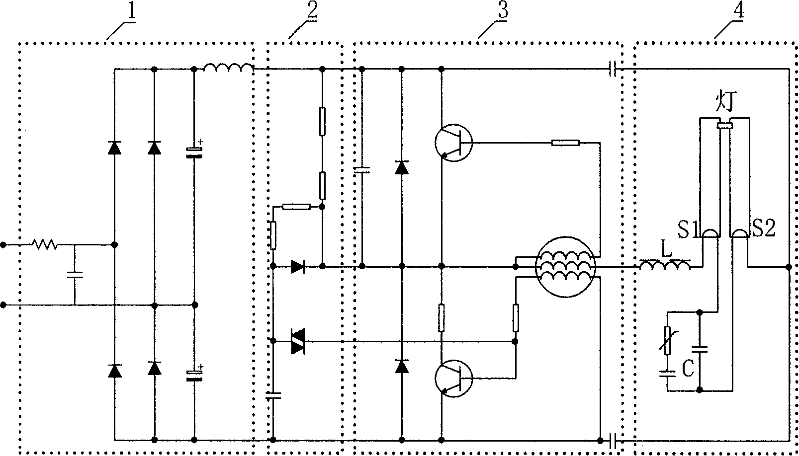
[0026] The following will combine Figure 4 with 5 The embodiment structure and working mode of the electronic ballast for abnormal protection of discharge lamp of the present invention will be described in detail.

[0027] Figure 4 A block diagram of the electronic ballast of this embodiment is shown. Such as Figure 4 As shown, the electronic ballast of this embodiment includes a power supply unit 1 , a starting unit 2 , an inverter unit 3 , a resonance unit 4 and a filament preheating and abnormality protection unit 5 .

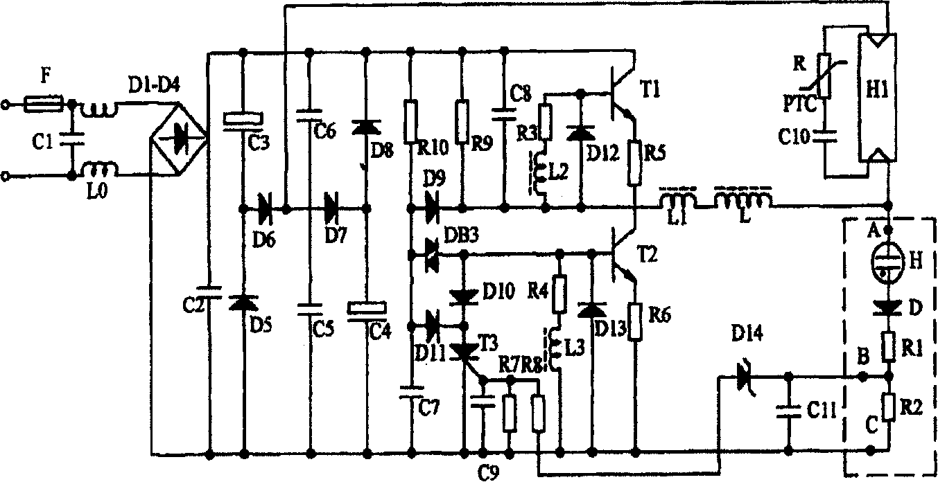
[0028] Figure 5 A detailed circuit diagram of the electronic ballast of this embodiment is shown.

[0029] Such as Figure 5As shown, in the case of using an AC power supply, the power supply unit 1 includes a rectification and filtering unit. The rectification and filtering unit includes a rectification bridge composed of four diodes D1, D2, D3 and D4, an electrolytic capacitor CD, and a filter inductor L0. The externally input alternating curre...


PUM


Abstract

The resonance unit of ballast includes: resonant capacitor (RC), in which first end is connected to an end of first filament of discharge lamp, and second end is connected to an end of second filament of discharge lamp; resonant inductor (RI), in which an end is connected to the first end of RC, and second end of RC and the other end of RI are connected to inversion unit to constitute closed loop. The ballast also includes filament warming up unit and abnormal protection unit (APU). APU includes warming and protecting branches connected to first and second filaments respectively to form closed loop. Each branch includes: drive part in use for generating drive signal in branches based on voltage at two ends of (RI); control part in use for controlling on/off of switching element in the inversion unit based on the drive signal; overflow protection element in use for shutting off the branch, in which current is larger than the specific value.

Description

technical field [0001] The invention relates to a circuit device for controlling a discharge lamp, in particular to an electronic ballast for abnormal protection of the discharge lamp, and also to a discharge lamp using the electronic ballast. Background technique [0002] Electronic ballast discharge lamps have widely replaced ordinary inductive ballast discharge lamps because of their high luminous efficiency, no flicker, high efficiency and energy saving. [0003] A discharge lamp circuit using an electronic ballast usually includes a power supply unit 1, a starting unit 2, an inverter unit 3 and a resonant load unit 4, such as figure 1 , figure 2 shown. In normal operation, after the electronic ballast is energized, the inverter unit 3 together with the inductance coil L, the filaments S1 and S2, and the capacitor C form a series resonant circuit. Use the high voltage generated at both ends of the starting capacitor during resonance to start the discharge lamp as a l...

Claims


Application Information

Patent Timeline
Patent Type & Authority Applications(China)
IPC IPC(8): H05B41/295H05B41/298
Inventor 孙清波
Owner PANASONIC CORP
Why Eureka
Try Eureka