
Decentralized power generation system

A power generation system, decentralized technology, applied in photovoltaic power generation, circuits, electrical components, etc., can solve the problems of instability, insufficient reliability of the inverter, and cannot be used for feeding, etc., to achieve long life and high reliability, simple Modularity, the effect of avoiding expensive parts

Inactive Publication Date: 2011-10-05
PHILIPS LIGHTING HOLDING BV
View PDF2 Cites 0 Cited by
  • Summary
  • Abstract
  • Description
  • Claims
  • Application Information

AI Technical Summary

Problems solved by technology

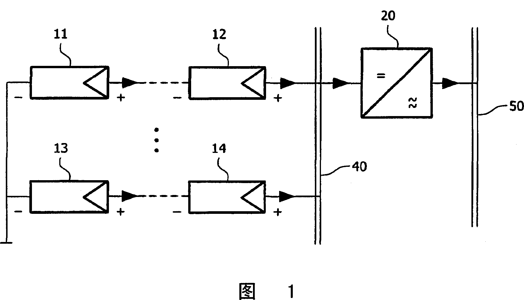
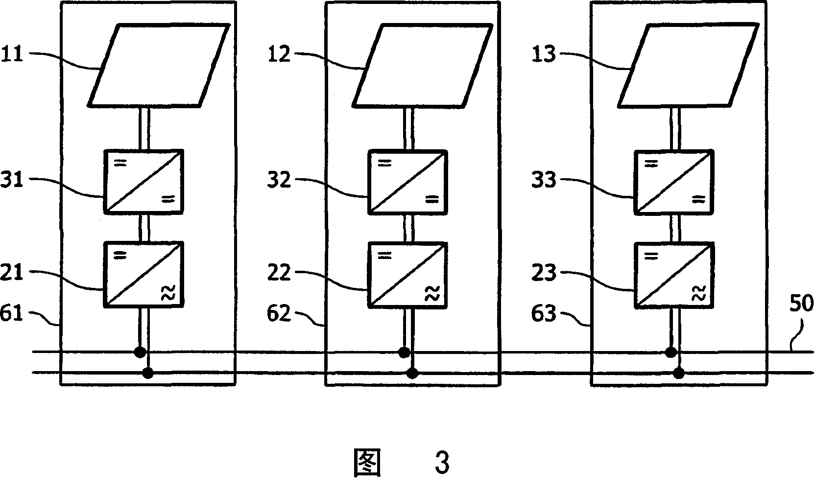
[0016] The disadvantage of such a PV power plant is that each inverter 21, 22, 23 must independently account for the need to feed current into the utility power system
Moreover, if the assigned inverters 21, 22, 23 have to be viewed and / or controlled from a central location, they must be connected to separate communication structures
Furthermore, when the control algorithms in the inverters 21, 22, 23 cause each other to oscillate, they may become unstable
[0017] image 3 Another disadvantage of the shown PV power plant is the insufficient reliability of the inverters 21, 22, 23 due to environmental strains when installed on the roof
Furthermore, similar problems can also occur if the energy generated by decentralized generation units (such as PV modules) is not used to feed into the utility power system, but is used for other purposes

Method used


Image

  • Decentralized power generation system
  • Decentralized power generation system
  • Decentralized power generation system

Examples


Embodiment Construction

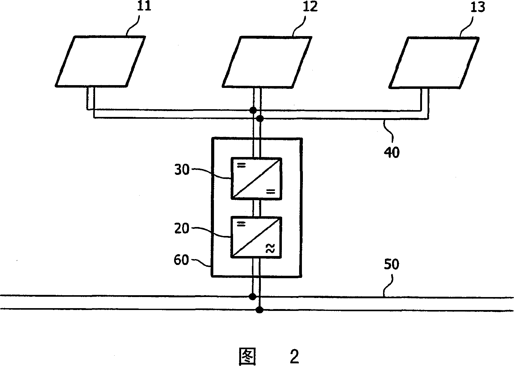
[0053] Figure 4 It is a block diagram of a PV power plant constituting an embodiment of the distributed power supply system according to the present invention.

[0054] The PV power plant comprises a first series connection of PV modules 11,12. Both ends of this first series connection are connected to the input of the first DC / DC converter 31. The PV power plant also includes a second series connection of PV modules 13,14. Both ends of this second series connection are connected to the input of the second DC / DC converter 32. The respective outputs of the DC / DC converters 31 and 32 are connected to the lines of the common DC bus 40. In addition, the PV module is connected to the DC bus 40 via an independent DC / DC converter in the same manner. The PV power plant finally includes an inverter 20. The input of the inverter 20 is similarly connected to the line of the DC bus 40, and the output of the inverter 40 is connected to the line 50 of the utility power system.

[0055] Ref...


PUM


Abstract

The invention relates to a decentralized power generation system comprising a plurality of decentralized power generating units (11,12;13,14). In order to enable an optimized control of these power generating units while enabling at the same time a high security in the system, a system is proposed that the system comprises a plurality of DC / DC converters (31,32), each connected to another one of the power generating units for converting a current provided by the power generating units. The proposed system moreover comprises a DC bus (40) to which the DC / DC converters feed a respectively converted current. The proposed system further comprises at least one power receiving component (20) retrieving current from the DC bus, which power receiving component is physically separated from the DC / DC converters. The invention relates equally to a corresponding method.

Description

Technical field [0001] The present invention relates to a decentralized power generation system including a plurality of decentralized power generation units. The invention also relates to a method of operating such a decentralized power generation system. Background technique [0002] A decentralized power generation system in the form of a photovoltaic (PV) power plant is known, for example. [0003] Photoelectric power is one of the most promising energy sources for renewable energy. In PV power plants, PV cells generate direct current, thereby generating a low direct current voltage of less than 1V in each cell. Therefore, multiple PV cells are usually assembled in a PV module. According to the implementation, such a PV module may have an output voltage of several tens of volts and provide power of 10W to 150W. [0004] In some applications, for example, in a PV power plant used to feed the generated current into a utility power system, the DC provided by the PV module is fur...

Claims


Application Information

Patent Timeline
IPC IPC(8): H02J1/10H02J3/02H02J3/38H02M7/493H01L31/042H02M7/48
CPCH02J3/383Y02E10/563H02J1/10H02J3/02Y02E10/58H02M7/493H02J3/385H02J2300/26H02J2300/24H02J3/381Y02E10/56
Inventor M·温德特P·吕尔肯斯
Owner PHILIPS LIGHTING HOLDING BV
Learn More