Ripple suppression circuit and method and switching power supply

A ripple suppression and circuit technology, applied in the field of electronics, can solve problems such as increasing power supply energy storage, increasing output ripple, and reducing power output ripple, so as to reduce ripple, improve reliability, and improve circuit modules. simple effect

Pending Publication Date: 2022-04-22
合肥移瑞通信技术有限公司
View PDF0 Cites 0 Cited by
  • Summary
  • Abstract
  • Description
  • Claims
  • Application Information

AI Technical Summary

Problems solved by technology

[0003] However, the current solutions to ripple have great limitations: on the one hand, power devices cannot greatly increase the operating frequency, resulting in the inability to reduce the output ripple of the power supply by increasing the operating frequency; on the other hand, although increasing the output filter capacitor can reduce Small ripple, but this method must obtain the ripple frequency characteristics through detailed and rigorous calculations, so as to select accurate resistance and capacitance values, but once the capacitor fails, the resistor fails or is slightly inaccurate, it is very likely to be mixed in new ripple or noise, but increases the output ripple
Moreover, this method will increase the energy storage of the power supply, and will release more energy when the load is short-circuited, which requires higher stress on the load, especially in the application of high-power switching power supplies, which has potential safety hazards and will also increase the size and size of the power supply. It is difficult to reduce the weight, resulting in an increase in the cost of the overall solution
[0004] In short, the existing switching power supply circuits that can eliminate or suppress ripples have poor reliability, high cost, and strict requirements on the application environment.

Method used


Image

  • Ripple suppression circuit and method and switching power supply
  • Ripple suppression circuit and method and switching power supply
  • Ripple suppression circuit and method and switching power supply

Examples


Embodiment Construction

[0031] In order to make the purpose, technical solutions and advantages of the embodiments of the present invention more clear, various implementation modes of the present invention will be described in detail below in conjunction with the accompanying drawings. However, those of ordinary skill in the art can understand that, in each implementation manner of the present invention, many technical details are provided for readers to better understand the present application. However, even without these technical details and various changes and modifications based on the following implementation modes, the technical solution claimed in this application can also be realized.

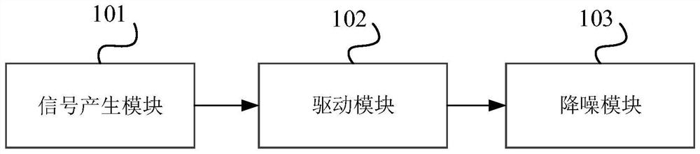
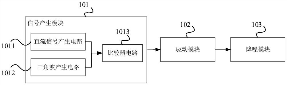
[0032] Embodiments of the present invention relate to a ripple suppression circuit such as figure 1 As shown, it specifically includes: a signal generating module 101 , a driving module 102 and a noise reduction module 103 .

[0033] Specifically, the input terminal of the signal generation module 101 recei...


PUM


Abstract

The embodiment of the invention relates to the technical field of electronics, and discloses a ripple suppression circuit and method and a switching power supply. The ripple suppression circuit comprises a signal generation module, a driving module and a noise reduction module which are connected in sequence, the signal generation module is used for receiving an input signal and generating a first pulse width modulation (PWM) signal and a second PWM signal which are opposite in phase; the driving module is used for amplifying the first PWM signal and the second PWM signal and obtaining a first driving signal and a second driving signal; and the noise reduction module is used for carrying out noise reduction on the first driving signal to obtain a first filtering signal, carrying out noise reduction on the second driving signal to obtain a second filtering signal, superposing the first filtering signal and the second filtering signal, and outputting the superposed signals. The invention aims to improve the reliability and the applicability of the ripple suppression switching power supply circuit and reduce the cost at the same time.

Description

technical field [0001] The embodiments of the present invention relate to the field of electronic technology, in particular to a ripple suppression circuit, method and switching power supply. Background technique [0002] Switching power supplies have the advantages of small size, light weight and high efficiency, and have been widely used in electronic equipment. However, the output voltage ripple of the switching power supply is relatively large, including low-frequency ripple, high-frequency ripple, common-mode noise, and noise generated by switching devices. In the prior art, the usual solution to the ripple of the switching power supply is mainly by increasing the switching frequency of the power supply or increasing the output filter capacitor. [0003] However, the current solutions to ripple have great limitations: on the one hand, power devices cannot greatly increase the operating frequency, resulting in the inability to reduce the output ripple of the power suppl...

Claims


Application Information

Patent Timeline
Patent Type & Authority Applications(China)
IPC IPC(8): H02M1/14H02M1/088H02M3/158
CPCH02M1/14H02M1/088H02M3/158
Inventor 孟磊郑雷
Owner 合肥移瑞通信技术有限公司
Why Eureka
Try Eureka