
Liquified natural gas pressure raising gasification process conprehensive energy using system in gas station

A technology for liquefied natural gas and gas filling stations, which is applied in gas/liquid distribution and storage, pressure vessels, fixed-capacity gas storage tanks, etc. It can solve the problems of installing complex purification systems and achieve the effect of reducing energy consumption

Inactive Publication Date: 2007-01-31
XI AN JIAOTONG UNIV
View PDF0 Cites 10 Cited by
  • Summary
  • Abstract
  • Description
  • Claims
  • Application Information

AI Technical Summary

Problems solved by technology

This kind of gas filling station needs to lay NG pipelines, and to install complex purification systems, special compressors and cooling equipment

Method used


Image

  • Liquified natural gas pressure raising gasification process conprehensive energy using system in gas station

Examples


Embodiment Construction

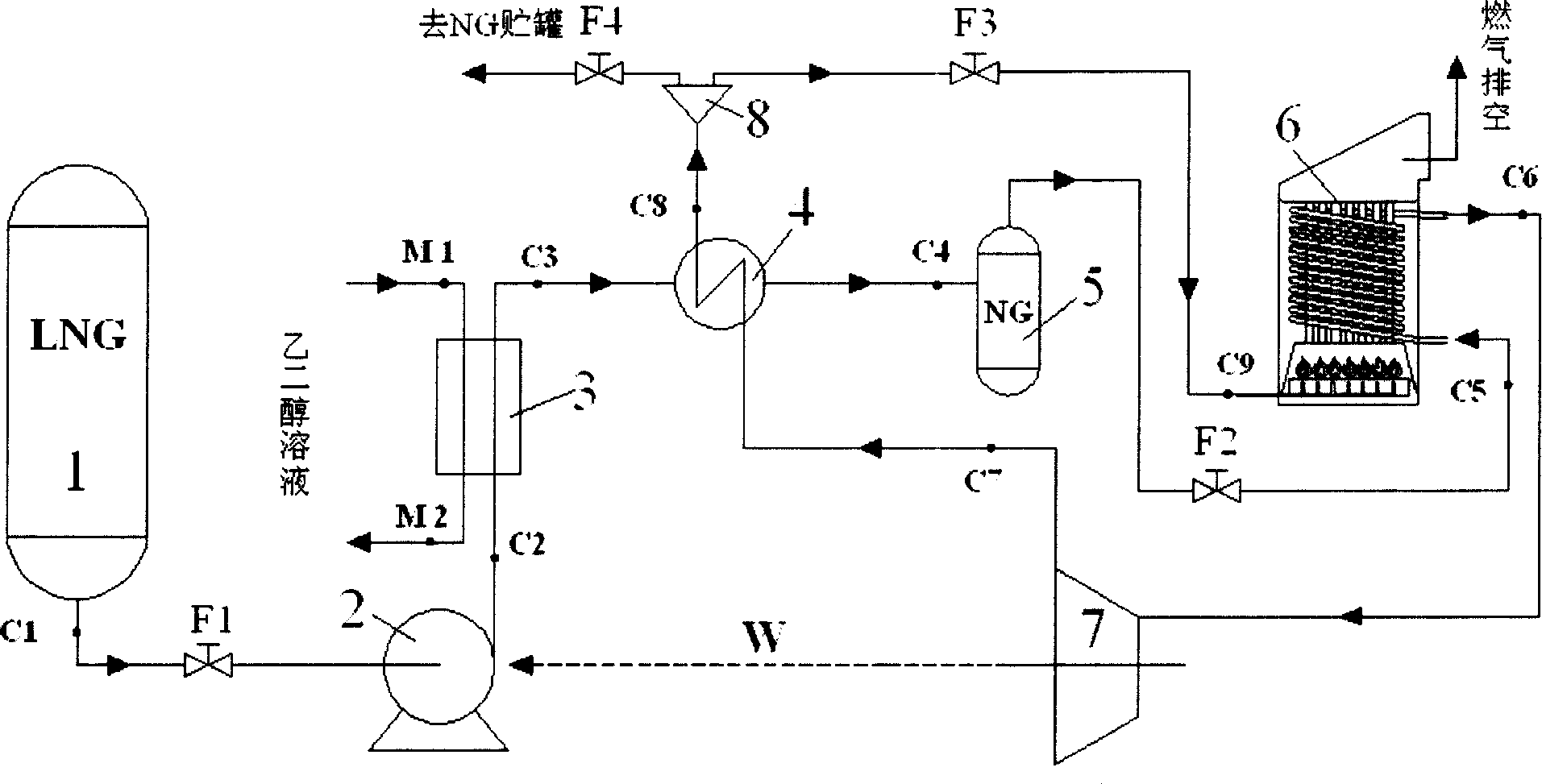
[0010] The comprehensive energy utilization system for LNG boosting gasification process in the gas filling station of the present invention comprises: LNG storage tank 1, low temperature liquid pump 2, low temperature heat exchanger 3, regenerator 4, high pressure gas storage tank 5, combustion chamber 6, Expander 7, diverter 8, LNG flow control valve F1, fuel gas regulating valve F3, flow control valves F2, F4 and connecting pipelines, etc.;

[0011] The sequence of connection methods of the above devices is: from the LNG outlet C1 at the bottom of the LNG storage tank 1, through the LNG flow control valve F1, connected to the cryogenic liquid pump 2, connected to the high-pressure LNG heat exchange channel C2→C3 of the cryogenic heat exchanger 3, connected to The high-pressure natural gas heat exchange channel C3→C4 of the regenerator 4 is connected to the high-pressure natural gas storage tank 5, through the flow control valve F2, connected to the high-pressure natural gas ...


PUM


Abstract

The invention comprises a LNG storage tank and a cryogenic liquid pump connected at the bottom outlet of the LNG storage through a flow control valve. The cryogenic liquid pump is in communication with a regenerator through a heat-exchanging channel of a low-temperature heat exchanger. The regenerator is connected with a high-pressure storage tank. A high-pressure natural gas storage tank is connected with a combustion chamber through the flow control valve and the combustion chamber is connected with an expansion machine. The outlet of the expansion machine is in communication with the regenerator and regenerator is also connected with a divider. One outlet of the divider is in communication with the combustion chamber through a fuel control valve and the other outlet is connected with a CNG buffer tank through the flow control valve.

Description

technical field [0001] The invention relates to LNG-CNG pressure boosting and system internal power comprehensive utilization technology, in particular to a comprehensive energy utilization system for LNG boosting gasification process in a gas filling station. Background technique [0002] Compressed Natural Gas (CNG for short) is natural gas that is pressurized (over 25MPa) and stored in a container in a gaseous state. It has the same composition as pipeline natural gas. CNG can be used as vehicle fuel. CNG has been widely used as fuel in buses in large and medium-sized cities across the country, and its technology is mature, stable and reliable. CNG refueling station is the base for refueling CNG vehicles, an essential part of the CNG vehicle industry, and the infrastructure for the use and development of CNG vehicles. At present, the process flow is as follows: the natural gas (NG) entering the station, after dust removal, desulfurization, dehy...

Claims


Application Information

Patent Timeline
IPC IPC(8): F17C7/04
Inventor 厉彦忠谭宏博梁骞鱼剑琳燕娜
Owner XI AN JIAOTONG UNIV
Learn More