Method and system of user access virtual special LAN service
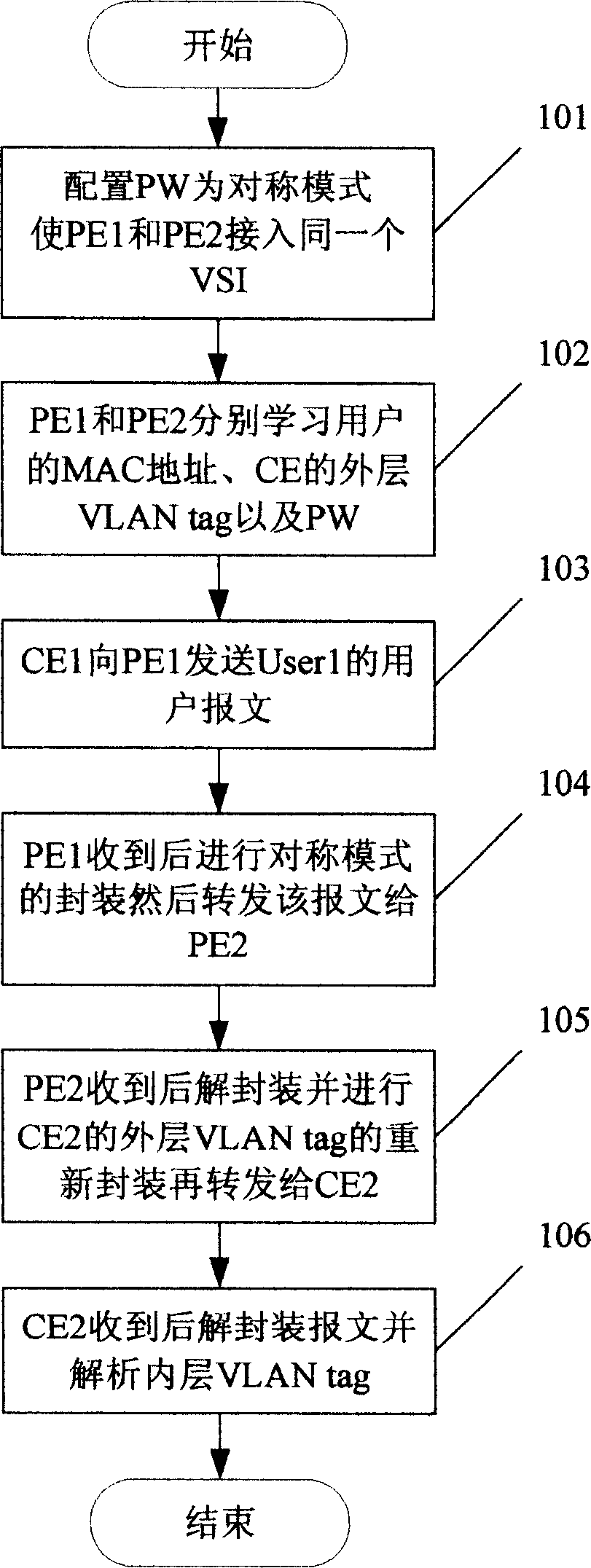
A virtual private and local area network technology, applied in the field of communication, which can solve the problems such as the inability of the PE to access the VSI with VLAN tags and the inability of the users at both ends to communicate with each other.
- Summary
- Abstract
- Description
- Claims
- Application Information
AI Technical Summary
Problems solved by technology
Method used
Image
Examples
Embodiment 1
[0074] see figure 2 It is a schematic diagram of a network topology structure of a user accessing a virtual private area network service provided by the present invention, PE1 and PE2 are two edge devices of the backbone network, A is an interface provided by PE1, and B is an interface provided by PE2. Set the two-layer VLAN tag to 1000 / 500-800 on interface A of PE2, and set the double-layer VLAN tag to 2000 / 500-800 on interface B of PE2 (in practical applications, one or more layers of VLAN tag can be set on PE , the present invention can also be realized, and in this embodiment, only two layers of VLAN tags are used for illustration), CE1 is a user network edge device connected to PE1, the VLAN tag is set on CE1 as 1000 / 500-600, and a user is connected below CE1 User1, the VLAN tag of User1 is 500; CE2 is a user network edge device connected to PE2, and the VLAN tag is set to 2000 / 500-700 on CE2, and a user User2 is connected to CE2; the inner VLAN tags of CE and PE are bot...
Embodiment 2
[0085] still with figure 2 The shown network topology structure is an example, wherein the VLAN tag of User2 is 501, and the present invention also provides another method for users to access virtual private local area network services, see Figure 4 , first perform the initialization steps:
[0086] Step 201: Configure the working mode of a PW between PE1 and PE2 as an asymmetric mode, and interface A of PE1 and interface B of PE2 access the same VSI through the PW;
[0087] Step 202: PE1 learns the MAC address of User1 and the two-layer VLAN tag 1000 / 500-600 of CE1, also learns the MAC address of User2 and the PW, and stores the learned content in the MAC forwarding table on PE1; PE2 Learn the MAC address of User2 and the two-layer VLAN tag 2000 / 500-700 of CE2, also learn the MAC address of User1 and the PW, and store the learned content in the MAC forwarding table on PE2;
[0088] Then perform the following steps:
[0089] Step 203: when User1 wishes to visit User2, CE1...
Embodiment 3
[0101] see Figure 5 , assuming that CE1 connected to PE1 is the headquarters of a company, and the user VLAN tag set on CE1 is 1000 / 500-600, and CE2 connected to PE2 is the R&D department of the company, and the user VLAN tag set on CE2 is 1000 / 200-300, CE3 connected to PE3 is the branch finance department of the company, and the user VLAN tag set on CE3 is 1000 / 200-300, the company requires user VLAN isolation between the two branches, that is, R&D The department and the financial department cannot communicate with each other, but there is no need to isolate user VLANs between the headquarters and each branch. An asymmetric PW can be established between PE1 and PE2 to implement intercommunication between CE1 and CE2. PE1 and PE3 Set up a PW in asymmetric mode to implement intercommunication between CE1 and CE3, and set up a PW in symmetric mode between PE2 and PE3 to implement VLAN isolation between CE2 and CE3.
PUM
 Abstract
Description
Claims
Application Information
 - R&D
- Intellectual Property
- Life Sciences
- Materials
- Tech Scout
- Unparalleled Data Quality
- Higher Quality Content
- 60% Fewer Hallucinations
Browse by: Latest US Patents, China's latest patents, Technical Efficacy Thesaurus, Application Domain, Technology Topic, Popular Technical Reports.
© 2025 PatSnap. All rights reserved.Legal|Privacy policy|Modern Slavery Act Transparency Statement|Sitemap|About US| Contact US: help@patsnap.com


