Rotating electric machine integral with control device

A technology for controlling devices and rotating electrical machines, applied in electromechanical devices, cooling/ventilating devices, electrical components, etc., can solve the problems of overheating of components, high prices, and heating of the main body of the rotating motor of the front bracket, and achieves the purpose of suppressing heat conduction and effectively cooling. Effect

Active Publication Date: 2007-01-31
MITSUBISHI ELECTRIC CORP
View PDF2 Cites 18 Cited by
  • Summary
  • Abstract
  • Description
  • Claims
  • Application Information

AI Technical Summary

Problems solved by technology

[0006] In this way, the front frame and the rear frame are easily affected by the heat generated by the main body of the rotating motor. When an inverter device with electronic components is mounted on the heat sink of the rear frame, some components may overheat and exceed the allowable temperature.
In addition, when the inverter device uses electronic components and substrates that can be used at high temperatures, there is a problem that the overall cost is high due to the high price of these components.

Method used


Image

  • Rotating electric machine integral with control device
  • Rotating electric machine integral with control device
  • Rotating electric machine integral with control device

Examples


Embodiment Construction

[0025] Embodiment 1

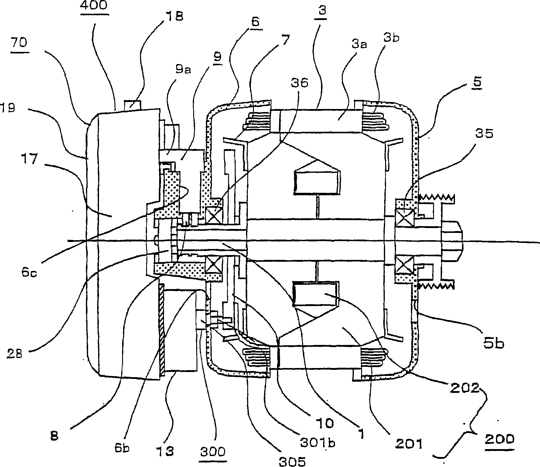
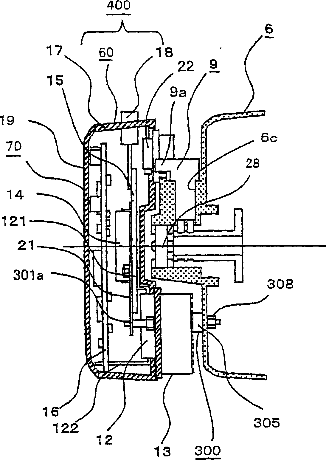
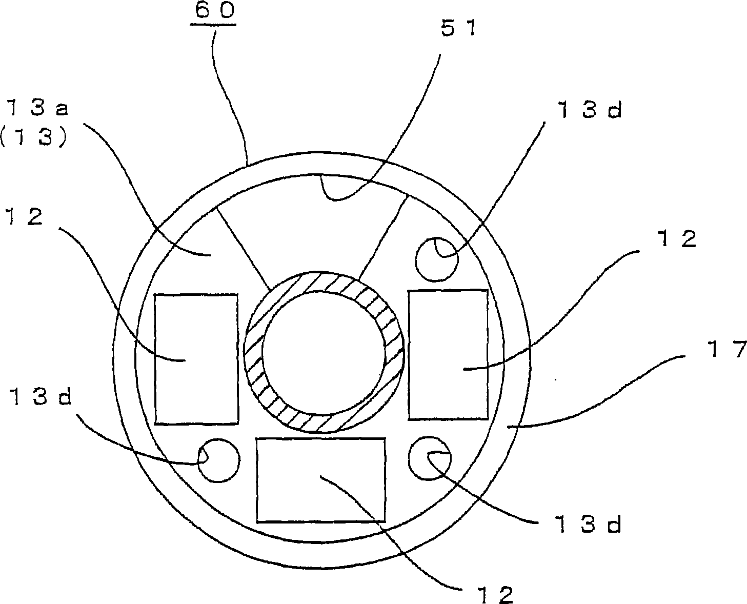
[0026] Figure 1 to Figure 10 Showing Embodiment 1 for carrying out the present invention, figure 1 is a partial cross-sectional view showing the configuration of a control-device-integrated rotating electrical machine, figure 2 is showing figure 1 A cross-sectional view of the detailed structure of the control device, image 3 It is a top view of the radiator periphery. Figure 4 is the top view of the radiator, Figure 5 It is a plan view showing the arrangement relationship between the switching element and the smoothing capacitor. Image 6 is the detailed structural diagram of the conductive stud bolt, Figure 7 It is an enlarged view of the mounting part where the radiator of the control unit is mounted on the rear bracket, Figure 8 It is an explanatory diagram for explaining the operation of fixing the conductive stud bolts to the heat sink. Figure 9 It is an explanatory diagram showing the flow of heat and cooling air of the rear bracket...


PUM


Abstract

The invention is intended to obtain a rotating electric machine with a built-in control device in which the control device is kept from receiving heat from a main body of the rotating electric machine and the control device can be cooled in a desirable fashion. A heat sink 13 on which switching devices 12 of a control device 400 are mounted is attached to a rear bracket 6 by means of conductive studs 300 with a particular spacing provided in a left-to-right direction of figure 2. The heat sink 13 is cooled by a flow of cooling air induced by an unillustrated fan. Since the control device 400 is attached to the rear bracket 6 of which temperature increases with the spacing provided therefrom, it is possible to suppress heat transfer from the rear bracket 6 and effectively cool the control device 400 through the heat sink 13.

Description

technical field [0001] The present invention relates to a control-device-integrated rotating electric machine, and more particularly, to a control-device-integrated rotating electric machine suitable for mounting on a vehicle. Background technique [0002] Examples of the control-device-integrated rotating electric machine for use in vehicles include the following electric machines. A stator with coils is fixed on the inner peripheral surface of the frame. A pair of bearing frames are fixed on both sides of the frame and support the rotating shaft of the rotor through bearings. On the outer side of the bearing frame (rear bracket) on the opposite load side of the above-mentioned bearing frames, protruding fins are integrally formed, and an inverter device for variable-speed operation of the rotating electric machine is attached to the fins. [0003] A cooling fan is installed on the protruding end of the rotating shaft on the opposite side of the load, and a fan cover with...

Claims


Application Information

Patent Timeline
Patent Type & Authority Applications(China)
IPC IPC(8): H02K11/00H02K9/06
CPCH02K11/048H02K9/06H02K5/22H02K11/05
Inventor 菊池正雄园田功
Owner MITSUBISHI ELECTRIC CORP
Why Eureka
Try Eureka