Flock blowing and heat radiation system for one-side circular knitting machine

A technology of heat dissipation system and circular knitting machine, used in textiles, papermaking, knitting, etc., can solve the problems of easy generation of cotton wool, high temperature of knitting needles, no blowing and cooling, etc.

Inactive Publication Date: 2007-02-07
PAI LUNG MACHINERY MILL CO LTD
View PDF0 Cites 4 Cited by
  • Summary
  • Abstract
  • Description
  • Claims
  • Application Information

AI Technical Summary

Problems solved by technology

However, the inventors have found that the most likely places to produce lint on the circular knitting machine are the yarn passing sheet, the yarn feeding nozzle, and the knitting needles, because holes are provided on the yarn passing sheet and the yarn feeding nozzle for weaving the cotton yarn through. , the cotton yarn will continue to rub against the yarn passing sheet and the hole on the yarn feeder to produce lint, and the knitting needle will easily produce lint when it rubs against the cotton yarn during the rotation and hooking process. High temperature; therefore, judging from the current existing blowing devices, there is no centralized air blowing and cooling for the position where cotton wool and high temperature are most likely to be generated on the circular knitting machine; in view of this, how to effectively blow cotton wool and cool down , which is actually a problem that urgently needs to be improved in the use of circular knitting machines today.

Method used


Image

  • Flock blowing and heat radiation system for one-side circular knitting machine
  • Flock blowing and heat radiation system for one-side circular knitting machine
  • Flock blowing and heat radiation system for one-side circular knitting machine

Examples


Embodiment Construction

[0019] The preferred embodiments and technical contents of the present invention are described as follows in conjunction with the accompanying drawings:

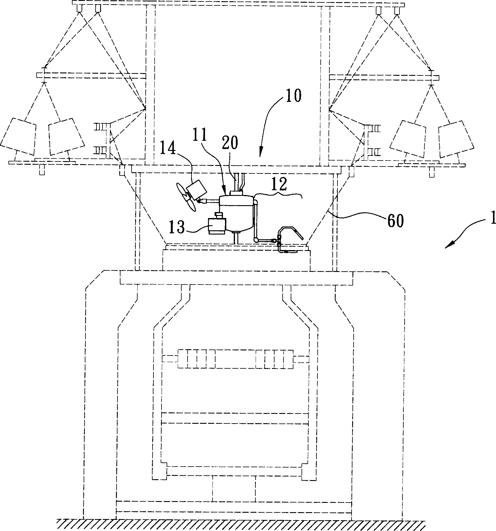
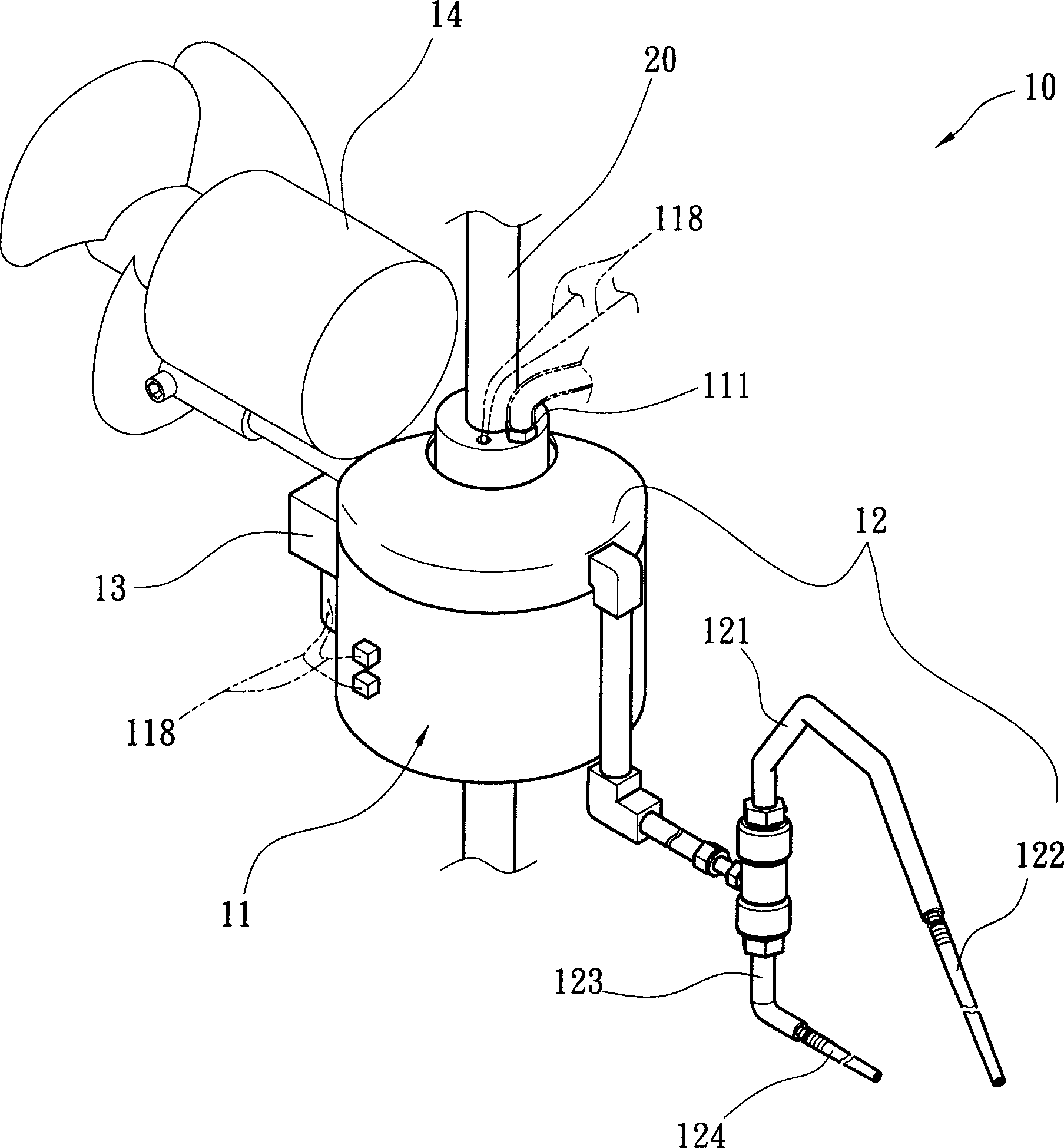
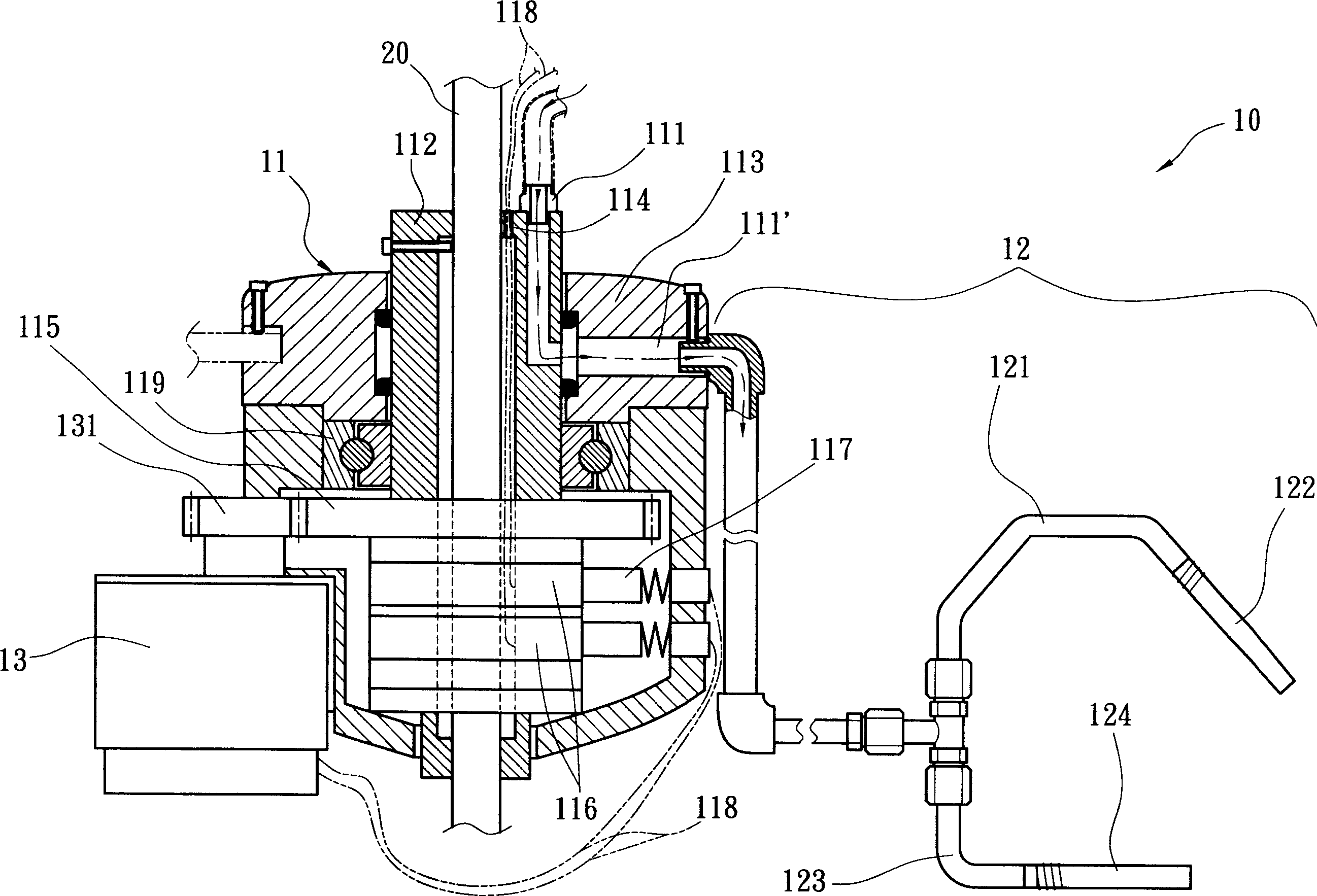
[0020] First, see figure 1 , figure 2 , image 3 ,and Figure 6 Shown are respectively the configuration, three-dimensional appearance, section, and a schematic diagram of an embodiment of the blowing and cooling system of the single-sided circular knitting machine according to the present invention. The present invention is particularly applicable to the single-sided circular knitting machine 1, The single-jersey circular knitting machine 1 is wound with several yarn passing pieces 30 for connecting the cotton yarn 60, a yarn feeder 40, and knitting needles 51 for rotating the hooked cotton yarn 60 for knitting, wherein the cotton yarn 60 passes through these yarn passing pieces respectively. The yarn-passing porcelain eye 31 of 30 and the yarn-feeding porcelain eye 41 holes of these yarn feeders 40;

[0021] The blowi...


PUM


Abstract

The invention relates to the blowing and heat emission system of single-surface circular knitting machine, which comprises: one fixing rod, one rotation supplier, and one blower, wherein the rotation supplier has one fixing axle, one rotation gas supplier, and one driving motor, while the fixing axle has one gas inlet above, the rotation gas supplier has one channel through to the gas inlet, and through to the blower, to drive the fixing axle via the driving motor, to blow the cotton wool from the yarn eye of yarn plate, the yarn eye of yarn open and the weave needle; in addition, the invention can reduce the heat generated by the friction between the rotation of needle cylinder and the weave needle.

Description

technical field [0001] The invention relates to a wadding blowing and heat dissipation system, in particular to a wadding blowing and heat dissipation system suitable for a circular knitting machine for weaving single jersey cloth. Background technique [0002] In the weaving process of the circular knitting machine, in order to improve the smoothness of the weaving operation, the cotton yarn supplied must be tensioned, and these cotton yarns often produce cotton wool during the process of yarn lowering, yarn guiding, and yarn feeding. If these If the cotton wool is not removed, it is easy to get stuck on the various parts of the circular knitting machine, which affects the smoothness of the knitting operation and shortens the life of the circular knitting machine. In addition, cotton batting and cotton yarn are woven into the finished cloth, which will also cause defects and affect the quality of the cloth. [0003] Based on the above problems, a variety of mechanisms for ...

Claims


Application Information

Patent Timeline
Patent Type & Authority Applications(China)
IPC IPC(8): D04B35/32D04B35/30
Inventor 陈世龙
Owner PAI LUNG MACHINERY MILL CO LTD
Why Eureka
Try Eureka