Rotating anchor rod of a rod and construction method thereof

A rod body and anchor rod technology, which is applied in the installation of anchor rods, excavation, earthwork drilling and mining, etc., to achieve the effects of avoiding underground hazards, small friction, and reducing recovery tension

Inactive Publication Date: 2007-02-07
曾庆义
View PDF1 Cites 12 Cited by
  • Summary
  • Abstract
  • Description
  • Claims
  • Application Information

AI Technical Summary

Problems solved by technology

[0007] The technical problem to be solved by the present invention is to overcome the defects of the existing rotary anchors and provide a rotary anchor with simple structural design, material saving, convenient construction and installation, recyclable rod body and can be used as a pressure anchor

Method used


Image

  • Rotating anchor rod of a rod and construction method thereof
  • Rotating anchor rod of a rod and construction method thereof
  • Rotating anchor rod of a rod and construction method thereof

Examples


Embodiment 1

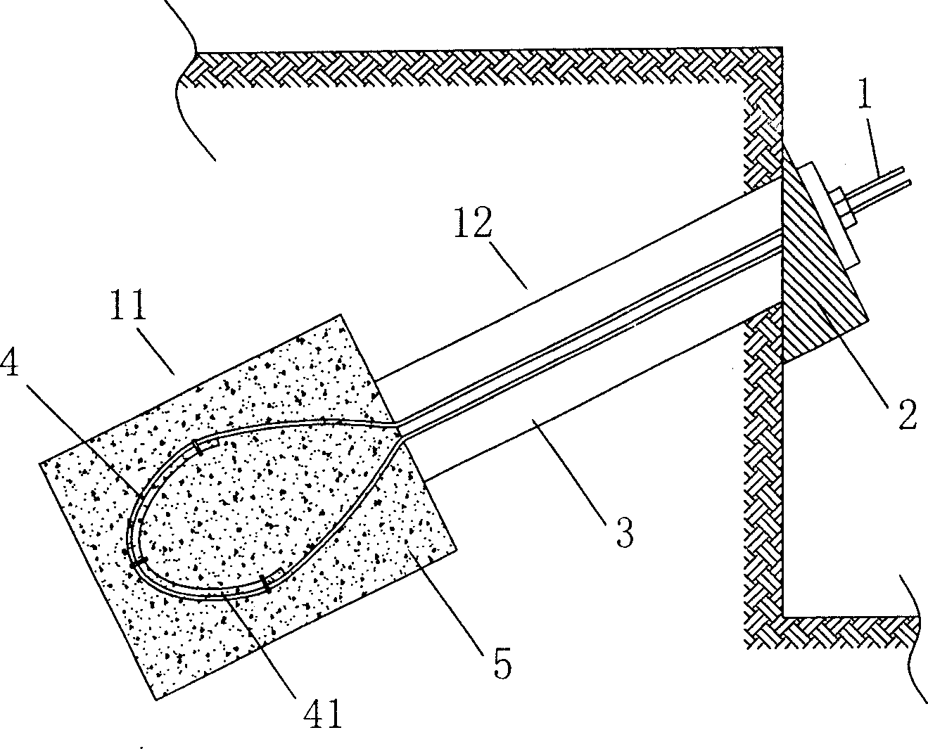
[0040] Such as figure 1 As shown, the present invention consists of a flexible anchor rod body 1, which is placed in the anchor hole after rotation, a grouting body 5 which is bonded to the anchor rod body after solidification of the grout poured into the anchor hole 3, and an anchor head fixing member 2 The anchor rod body 1 is composed of rotatably bent steel strands, wire ropes, wire bundles or engineering plastics, and is placed in the anchor hole 3. The anchor hole 3 is divided into an anchor section 11 and a free section 12. The anchor rod body 1 The straight section is placed in the free section 12, the revolving section is placed in the anchor hole anchor section 11, and the end is placed outside the anchor hole 3, which is convenient for control during recovery. It is characterized in that: on the revolving section of the anchor rod body 1, A supporting member 4 is provided, and the supporting member 4 can be deformed according to the rotation shape of the anchor rod body...

Embodiment 2

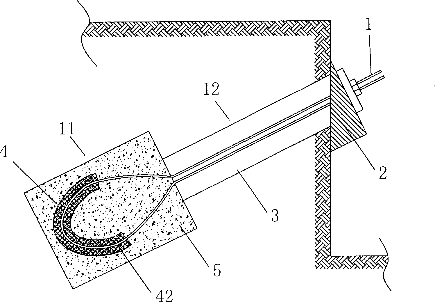
[0048] Such as figure 2 As shown, the anchor rod body 1, the grouting body 5, and the anchor head fixing member 2 of this embodiment are the same as those in the first embodiment, except that: the support member 4 can cover the surface of the rotating section of the anchor rod body 1 The mesh member 42, as shown in the figure, the mesh member 42 can be an elastic and bendable mesh. The mesh can be made of metal wire or other materials, and it can also be a three-dimensional with a certain thickness. A flexible mesh-shaped member. When the mesh is thin, it can be wrapped in multiple layers, or it can be repeatedly wound by the mesh. It can be attached to the anchor rod body 1 by wire tying or other fastening methods. The outer surface of the section is deformed according to the rotation shape of the anchor rod body 1, and the mesh aperture on it can fully penetrate and penetrate the slurry. When the rotary anchor rod is placed in the anchor hole 3, the net-shaped member 42 can be ...

Embodiment 3

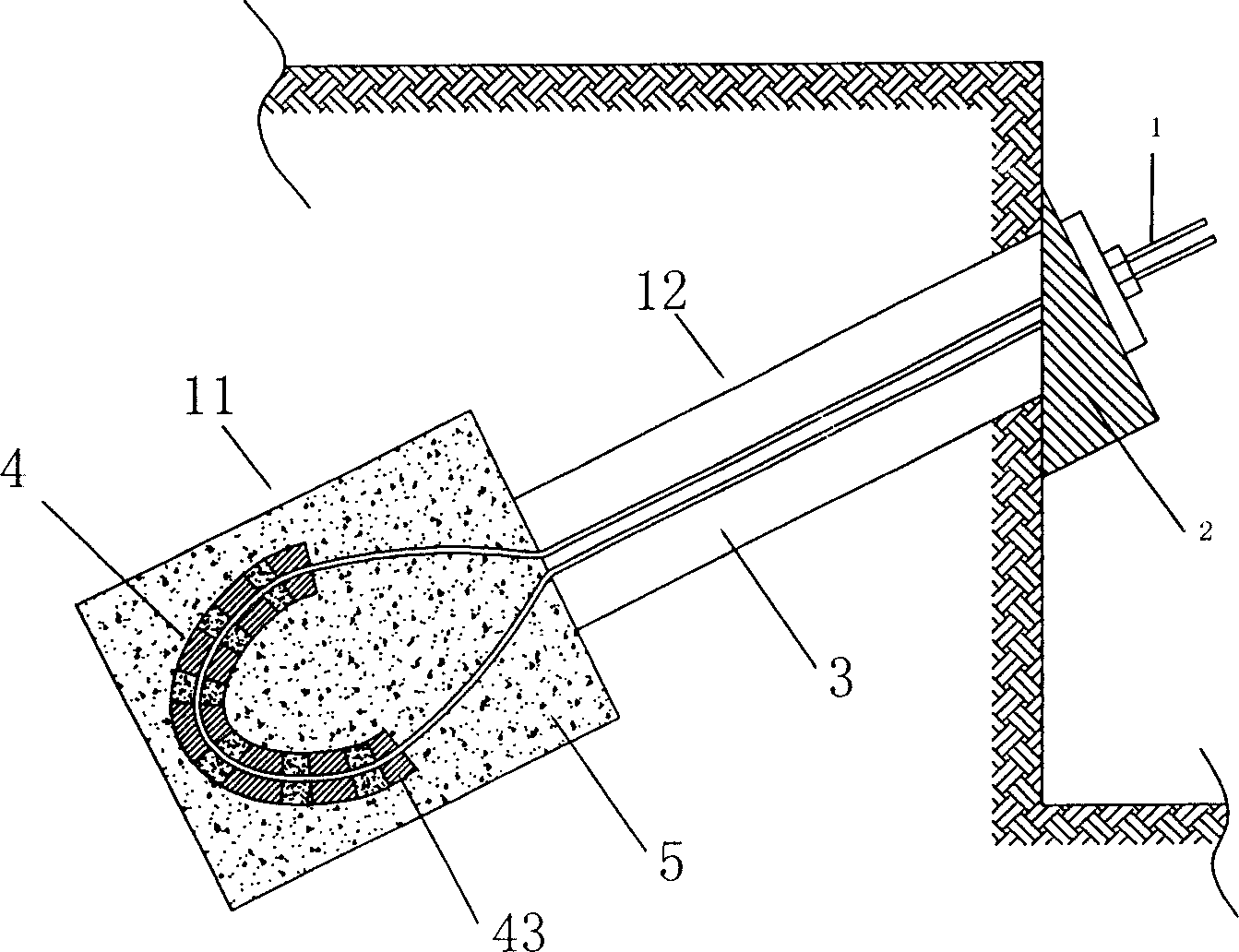
[0056] Such as image 3 As shown, the anchor rod body 1, the grouting body 5, and the anchor head fixing member 2 of the present embodiment are the same as the first and second embodiments, except that: the support member 4 is a sleeve covering the surface of the rotating section of the rod body Cylinder 43, as shown in the figure, the sleeve 43 can be a perforated elastic sleeve or the side wall of the sleeve has a mesh structure, which can be attached to the outside of the rotation section of the anchor rod body 1 through wire ties or other fastening methods The surface is deformed according to the rotation shape of the anchor rod body 1, and the upper aperture can accommodate the slurry to fully penetrate and penetrate. When the rotary anchor rod is placed in the anchor hole 3, the sleeve 43 can be combined with the grout during grouting, so that the consolidated body after grouting is formed as a carrier with a sleeve skeleton, which improves the grout 5 The strength of the an...


PUM


Abstract

The invention relates to an anchor rod whose rod is rotational, which comprises a rotated rod inside the anchor hole; the end of rod is outside the anchor hole; the straight section is in the free section of anchor hole; the rotation section is at the anchor section. And it is characterized in that: at the rotation section, it has the support element which can deform according to the rotation of rod; said support element is combined with the slurry element poured into the anchor hole, to form the support to support the drawing force of anchor rod; and said support is at the inner side of rotation section, to be cylinder, column, ball, or U-shaped, or at the inner side of rotation section to expand the rotation section, as one flexible element, or the mesh element at the surface of rotation section, or the mesh muffle at the surface, or the annular or screw element coiled on the surface of rotation section. The invention has simple structure and easy construction, while the rod can be recycled, and it can be used as pressure anchor rod.

Description

【Technical Field】 [0001] The invention relates to the field of soil or rock engineering foundation and side slope support, in particular to a rotatable anchor rod for support and a construction method using the anchor rod, and is mainly used in geotechnical engineering, foundation pits, slopes, etc. Engineering field. 【Background technique】 [0002] The anchoring technology in the foundation treatment method is to fix one end of the tensioned anchor rod in the rock or soil layer of the slope or foundation, and the other end is connected with the structure, and the anchoring force is used to withstand the application of earth pressure, water pressure or wind It and the thrust of the structure to maintain the stability of the structure. But generally speaking, after the mission of the anchor rod is completed, it will be permanently buried in the concrete, which not only wastes materials, but also causes damage to the underground environment. At the same time, the long anchor rod ma...

Claims


Application Information

Patent Timeline
Patent Type & Authority Applications(China)
IPC IPC(8): E02D5/74E02D17/20E21D21/00
Inventor 曾庆义
Owner 曾庆义
Why Eureka
Try Eureka