Solid wood composite floor fit for geothermal heat and manufacturing method thereof

A technology of solid wood composite flooring and manufacturing methods, applied in the direction of manufacturing tools, building structures, wood processing appliances, etc., can solve problems such as unfavorable heat transfer, achieve the effects of saving hardwood resources, broadening application fields, and good biological durability

Inactive Publication Date: 2007-02-07
ZHEJIANG FORESTRY UNIVERSITY +1
View PDF0 Cites 20 Cited by
  • Summary
  • Abstract
  • Description
  • Claims
  • Application Information

AI Technical Summary

Problems solved by technology

[0003] The object of the present invention is to propose a solid wood composite floor suitable for geothermal heating and its manufacturing method, which can effectively overcome the warping a...

Method used


Image

  • Solid wood composite floor fit for geothermal heat and manufacturing method thereof
  • Solid wood composite floor fit for geothermal heat and manufacturing method thereof

Examples


Embodiment 1

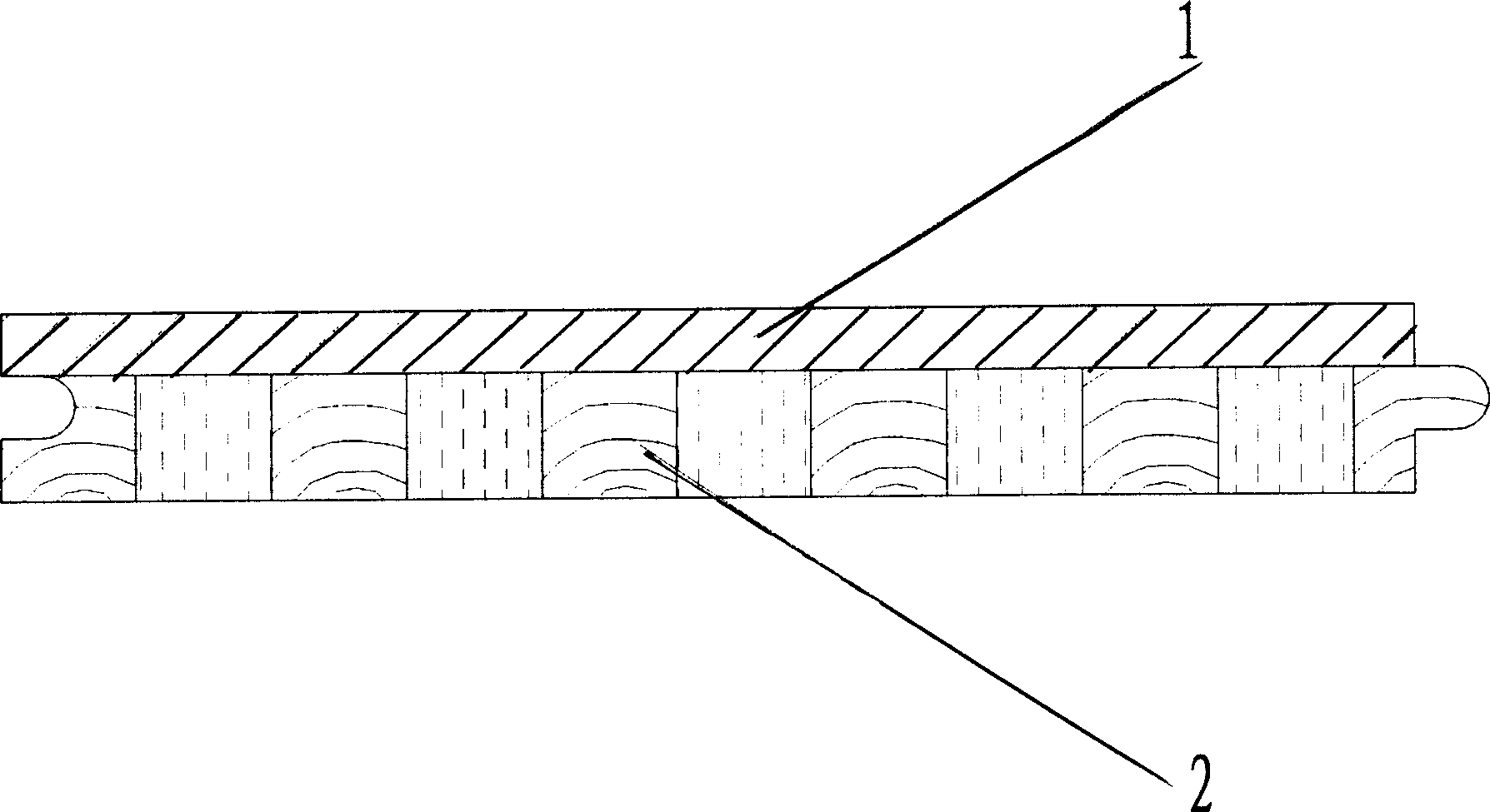
[0022] The double-layer structure solid wood composite floor suitable for geothermal heating, its manufacturing method is divided into 1, the preparation of the solid wood composite floor surface board; 2, the preparation of the composite floor base material; 3, the preparation of the composite floor.

[0023] One of them, the preparation of the solid wood composite floor surface board: dry the surface board blank with a width of 90 mm and a thickness of 25 mm to make its moisture content 12%, and divide it into 6 mm thick surface board products with a frame saw or a splitting machine.

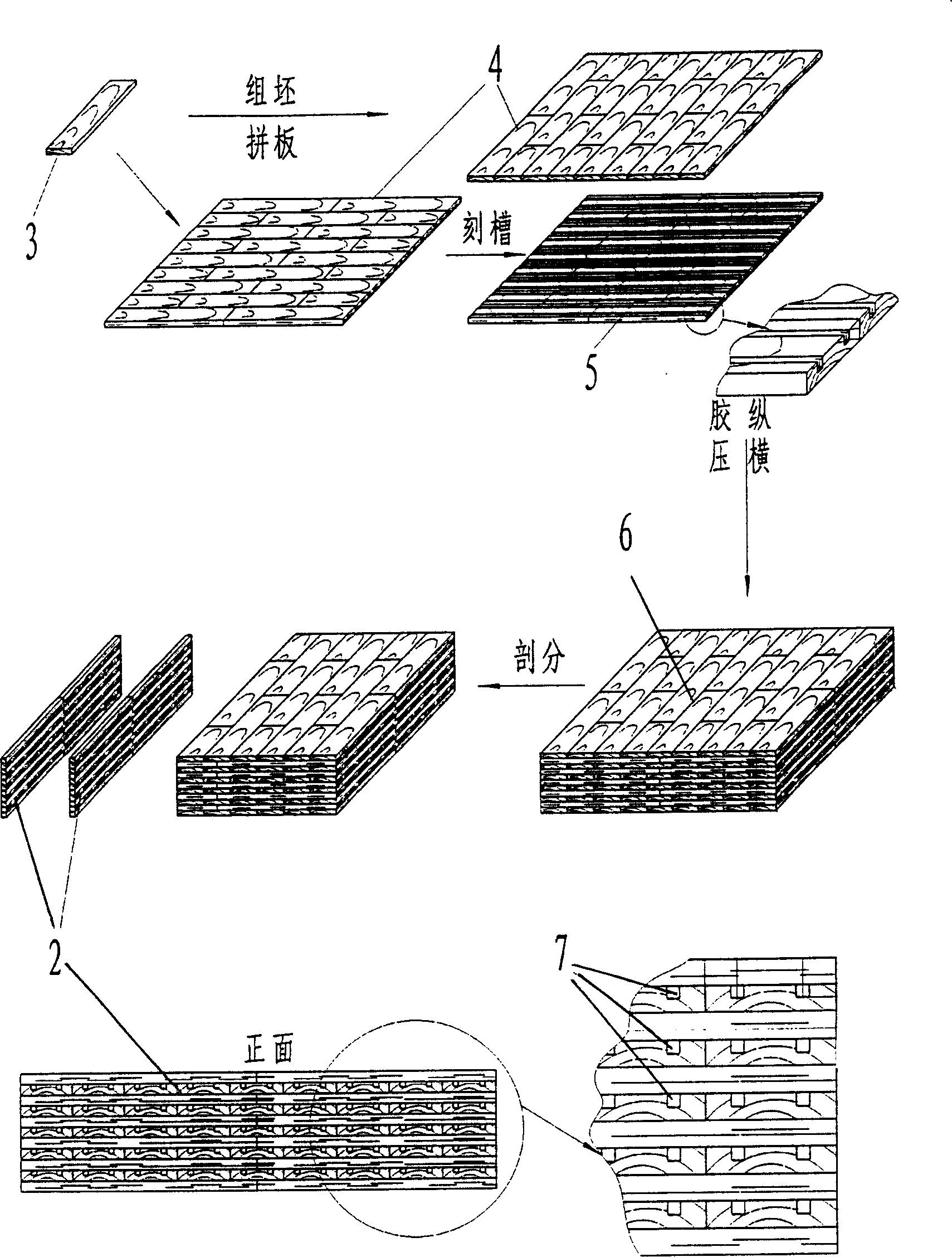
[0024] 2. Preparation of composite floor base material: a composite structure spliced ​​with fast-growing wood and solid wood is adopted, specifically carbonizing the fast-growing wood carbonized wood blank, and the treatment temperature is 240° C.; mechanically processing the carbonized blank to obtain a thin plate 3, Coat the side of sheet 3 with urea-formaldehyde resin glue, the amount of gl...

Embodiment 2

[0027] The double-layer structure solid wood composite floor suitable for geothermal heating, its manufacturing method is divided into 1, the preparation of the solid wood composite floor surface board; 2, the preparation of the composite floor base material; 3, the preparation of the composite floor.

[0028] One of them, the preparation of solid wood composite floor boards: dry the board blanks with a certain size such as 200mm wide and 150mm thick to make their moisture content 6%, and split them into 3mm thick finished boards with a frame saw or splitter.

[0029] 2. Preparation of composite floor base material: a composite structure spliced ​​with fast-growing wood and solid wood is adopted, specifically carbonizing the fast-growing wood carbonized wood blank, and the treatment temperature is 160° C.; mechanically processing the carbonized blank to obtain a thin plate 3, Apply urea-formaldehyde resin glue to the side of the thin plate 3, and the amount of glue applied is 3...

Embodiment 3

[0032] The three-layer structure solid wood composite floor suitable for geothermal heating is manufactured by pasting a layer of rotary-cut wood veneer or thin wood veneer with a thickness of 2 to 3 mm on the bottom of the carbonized wood base plate 2 on the basis of the double-layer structure. board.


PUM

PropertyMeasurementUnit
Thicknessaaaaaaaaaa
Thicknessaaaaaaaaaa
Thicknessaaaaaaaaaa

Abstract

The invention relates to a solid composite floor and relative production, wherein the surface plate is above the carbonized bottom plate that adhered by adhesive; the bottom plate has vertical ventilate holes; the bottom plate is sliced by carbonized blank, then adhered by adhesive into single-layer plate; then assembling the single-layer plate with grooved single-layer plate alternatively into blank, with odd layers; and the non-groove single-layer plates are two outer surfaces of bottom plate; the grooved single-layer plate is grooved along the fiber direction, and formed by several sheets; the lower layer of bottom plate is adhered with one layer of shear single plate. The invention has better size stability, with local diversion heat exchange between the ground and the surface plate.

Description

technical field [0001] The invention relates to a specific structure and manufacturing method of solid wood composite floor, especially suitable for ground heating. Compared with the existing wooden floor technology, this kind of solid wood composite floor not only saves precious surface board resources, but also has good biological durability, weather resistance and dimensional stability. In addition, due to the special vent structure in the base material (bottom plate) of the composite floor, local convective heat exchange is formed between the ground and the surface plate, which further reduces the temperature difference between the upper and lower surfaces of the floor. The utility model belongs to the technical field of manufacturing solid wood compound flooring. Background technique [0002] At present, known wood flooring can be roughly divided into three categories: solid wood flooring, solid wood composite flooring and laminated flooring. The so-called solid wood ...

Claims


Application Information

Patent Timeline
IPC IPC(8): E04F15/04B27M3/04
Inventor 张齐生孟荣富伊松林鲍炳福
Owner ZHEJIANG FORESTRY UNIVERSITY
Why Eureka
Try Eureka