Channel estimating and detecting method for multiple-input multiple-output system

A channel estimation and detection method technology, applied to baseband system components, preventing/detecting errors through diversity reception, etc., can solve the problems of increasing the amount of calculation, increasing the number of training sequences, etc.

Inactive Publication Date: 2007-02-07
PANASONIC CORP
View PDF0 Cites 8 Cited by
  • Summary
  • Abstract
  • Description
  • Claims
  • Application Information

AI Technical Summary

Problems solved by technology

The high frequency of channel estimation will increase the computational load of the system. In add...

Method used


Image

  • Channel estimating and detecting method for multiple-input multiple-output system
  • Channel estimating and detecting method for multiple-input multiple-output system
  • Channel estimating and detecting method for multiple-input multiple-output system

Examples


Embodiment Construction

[0040] The principle of the present invention will be described below with reference to the accompanying drawings.

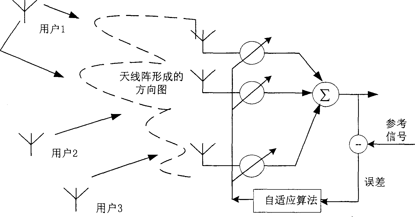
[0041] Assume that the base station has N antenna elements to receive the signal sent by the mobile station, and the wireless channel is a flat-fading Rayleigh channel. After matched filtering and sampling, the complex vector of the received signal expressed by the following formula (1) is obtained

[0042] y = E b bh + n - - - ( 1 )

[0043] where E b is the transmitted energy of each symbol, b is the transmitted symbol, and is the PSK (phase shift keying) modulation method. Suppose the channel vector h=[h 1 h 2 … h N ] T is a column vector, which is the instantaneous superposition of P multipaths,

[0044] h = 1 ...


PUM


Abstract

The invention relates to the signal channel evaluating and checking method of multi-input multi-output system, wherein it comprises: when evaluating and checking the signal channel of multi-input multi-output system, based on receiving signal, obtaining the related matrix of receiving signal; then processing characteristic decomposition on the matrix to obtain one or several characteristic vectors with larger characteristic value; said vector is relative to the signal channel stat independent component; and using said component to process idle treatment on the receiving signal to check received data.

Description

technical field [0001] The present invention relates to a channel estimation and signal detection method of a MIMO (Multiple Input Multiple Output) system, in particular, relates to a method for realizing channel estimation and detection in a related MIMO system in an actual environment, which can be applied to wireless Various systems in the environment, such as 3GPP, 3GPP2 and WiMax systems, etc. Background technique [0002] In order to improve the reuse rate of the spectrum, people think of using multiple transceiver antennas on one or both sides of the communication, and actively use the spatial orientation information of the user or the redundancy of the spatial channel to increase the capacity of the system. This is MIMO (Multiple Input Multiple output) for multi-antenna systems. The implementation of MIMO antenna system is divided into multiple levels. The current research hotspot and the most potential method are beamforming technology using adaptive array and mult...

Claims


Application Information

Patent Timeline
IPC IPC(8): H04L25/02H04L1/06
Inventor 赵铮李继峰
Owner PANASONIC CORP
Why Eureka
Try Eureka